GE Power Management
MM2 Motor Manager 2 6-37
6 COMMUNICATIONS 6.5 MEMORY MAP
6
PROCESS
INTER-
LOCK
NAMES
44513 4512 11A0 Intlck Counter Name chars 1 and 2 32-255 1 ASCII F10 “IN”
44514 4513 11A1 Intlck Counter Name chars 3 and 4 32-255 1 ASCII F10 “TE”
44515 4514 11A2 Intlck Counter Name chars 5 and 6 32-255 1 ASCII F10 “RL”
44516 4515 11A3 Intlck Counter Name chars 7 and 8 32-255 1 ASCII F10 “OC”
44517 4516 11A4 Intlck Counter Name chars 9 and 10 32-255 1 ASCII F10 “K “
44518 4517 11A5 Intlck Counter Name chars 11 & 12 32-255 1 ASCII F10 “CO”
44519 4518 11A6 Intlck Counter Name chars 13 & 14 32-255 1 ASCII F10 “UN”
44520 4519 11A7 Intlck Counter Name chars 15 & 16 32-255 1 ASCII F10 “TE”
44521 4520 11A8 Intlck Counter Name chars 17 & 18 32-255 1 ASCII F10 “R “
44522 4521 11A9 Intlck Counter Name chars 19 & 20 32-255 1 ASCII F10 ““
44523 4522 11AA Intlck Counter Units chars 1 and 2 32-255 1 ASCII F10 “UN”
44524 4523 11AB Intlck Counter Units chars 3 and 4 32-255 1 ASCII F10 “IT”
44525 4524 11AC Intlck Counter Units chars 5 and 6 32-255 1 ASCII F10 “S “
44526 4525 11AD Intlck Counter Units chars 7 and 8 32-255 1 ASCII F10 ““
44527 4526 11AE Intlck Counter Units chars 9 and 10 32-255 1 ASCII F10 ““
44528 4527 11AF ...Reserved... ... ... ... ... ...
AUX 2
RELAY
44529 4528 11B0 AUX Relay 2 Function 0-33 1 --- F20 0=serial cntl
44530 4529 11B1 AUX Relay 2 Delay 0-125 1 s F1 5
44531 4530 11B2 AUX Relay 2 Motor Start Delay 0-125 1 s F1 5
44532 4531 11B3 AUX Relay 2 Motor Stop Delay 0-125 1 s F1 5
44533 4532 11B4 AUX Relay 2 Pre Delay 0-900 1 s F1 5
44534 4533 11B5 AUX Relay 2 Post Delay 0-126 1 s F1 * 126 = OFF
44535 4534 11B6 AUX Relay 2 Operation 0-1 1 --- F12 0=non-failsafe
44536 4535 11B7 ...Reserved... ... ... ... ... ...
↓↓↓ ↓ ↓ ↓ ↓↓ ↓
44544 4543 11BF ...Reserved... ... ... ... ... ...
PROG.
INPUTS
44545 4544 11C0 Interlock 1 Switch Type 0-1 1 - F30 0 = N.O.
44546 4545 11C1 Interlock 2 Switch Type 0-1 1 - F30 0 = N.O.
44547 4546 11C2 Interlock 3 Switch Type 0-1 1 - F30 0 = N.O.
44548 4547 11C3 Interlock 4 Switch Type 0-1 1 - F30 0 = N.O.
44549 4548 11C4 Interlock 5 Switch Type 0-1 1 - F30 0 = N.O.
44550 4549 11C5 Interlock 6 Switch Type 0-1 1 - F30 0 = N.O.
44551 4550 11C6 Interlock 7 Switch Type 0-1 1 - F30 0 = N.O.
44552 4551 11C7 Interlock 8 Switch Type 0-1 1 - F30 0 = N.O.
44553 4552 11C8 Interlock 9 Switch Type 0-1 1 - F30 0 = N.O.
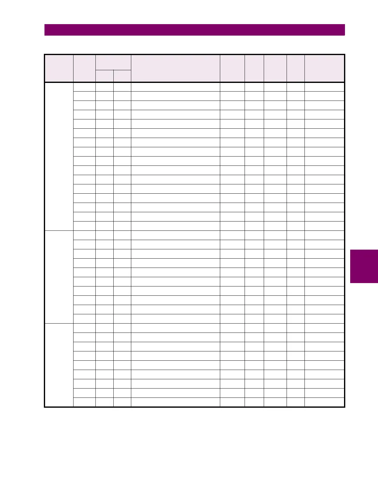
Table 6–12: MODBUS MEMORY MAP (Sheet 18 of 21)
GROUP MOD-
ICON
REGISTER
ADDRESS DESCRIPTION REGISTE
R VALUE
RANGE
STEP
VALUE
UNITS
AND
SCALE
FOR-
MAT
FACTORY
DEFAULT
VALUE
(CONVERTED)
DEC HEX
Notes: * – Maximum setpoint value and 65535 represent OFF
** – 1/Phase Current Scale Factor x A
*** – 101 represents unlimited
† – Minimum setpoint value represents OFF
~* – 0.1 x A when Hi resolution mode is disabled; 0.01 x A when enabled

 Loading...


