1–2 EPM 2200 POWER METER – INSTRUCTION MANUAL
WYE CONNECTION CHAPTER 1: THREE-PHASE POWER MEASUREMENT
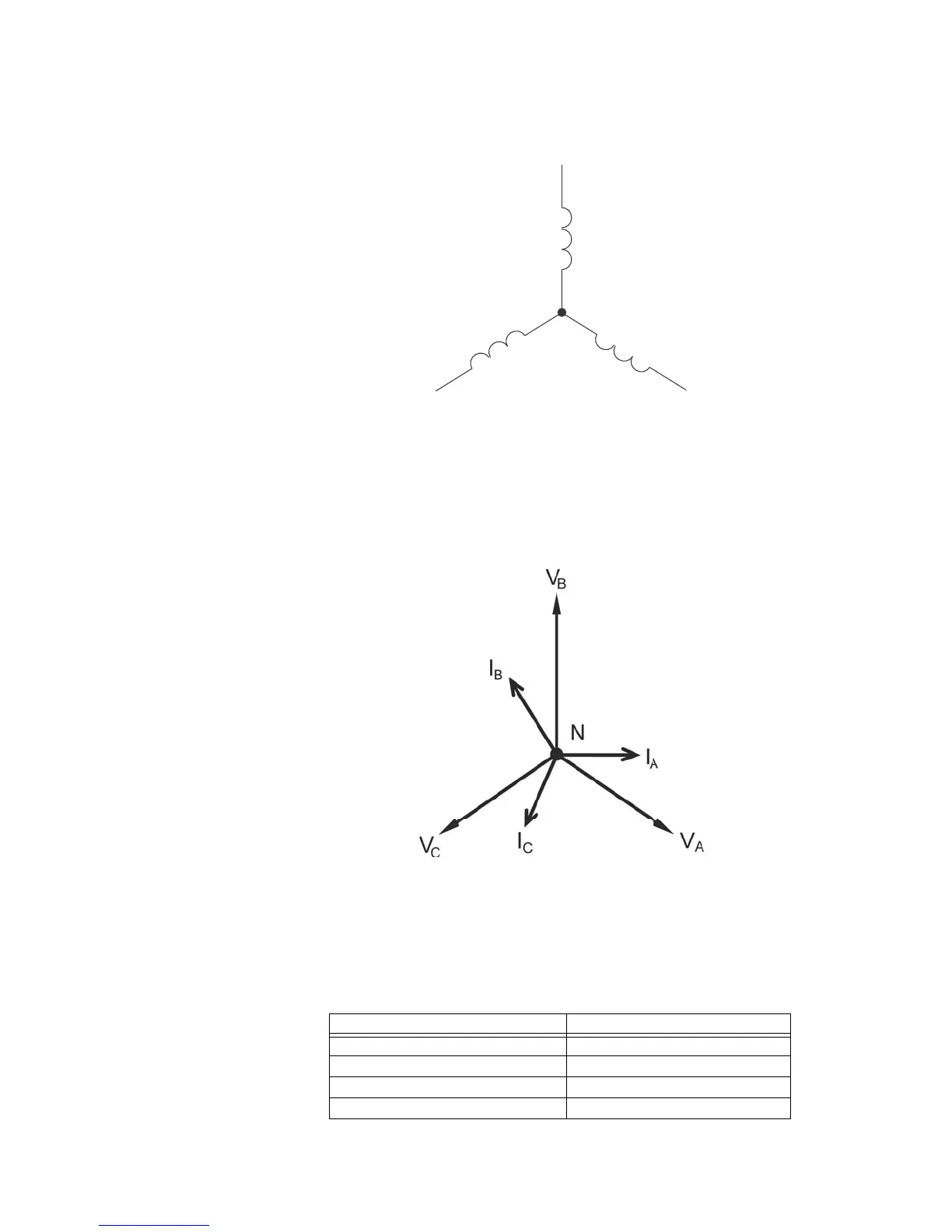
Figure 1-1: Three-phase Wye Winding
The three voltages are separated by 120
o
electrically. Under balanced load conditions
the currents are also separated by 120
o
. However, unbalanced loads and other
conditions can cause the currents to depart from the ideal 120
o
separation. Three-
phase voltages and currents are usually represented with a phasor diagram. A phasor
diagram for the typical connected voltages and currents is shown in Figure 1.2.
Figure 1-2: Phasor Diagram Showing Three-phase Voltages and Currents
The phasor diagram shows the 120
o
angular separation between the phase voltages.
The phase-to-phase voltage in a balanced three-phase wye system is 1.732 times the
phase-to-neutral voltage. The center point of the wye is tied together and is typically
grounded. Table 1.1 shows the common voltages used in the United States for wye-
connected systems.
Table 1.1: Common Phase Voltages on Wye Services
Phase to Ground Voltage Phase to Phase Voltage
120 volts 208 volts
277 volts 480 volts
2,400 volts 4,160 volts
7,200 volts 12,470 volts
N
Phase 1
Phase 3
V
C
 Loading...


