CHAPTER 7: MODBUS COMMUNICATIONS MODBUS MEMORY MAP
PQM POWER QUALITY METER – INSTRUCTION MANUAL 7–71
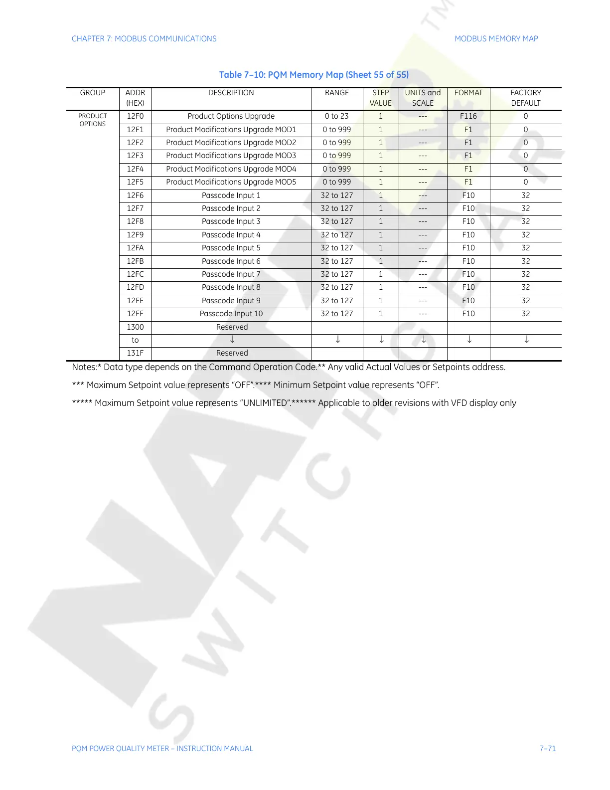
PRODUCT
OPTIONS
12F0 Product Options Upgrade 0 to 23 1 --- F116 0
12F1 Product Modifications Upgrade MOD1 0 to 999 1 --- F1 0
12F2 Product Modifications Upgrade MOD2 0 to 999 1 --- F1 0
12F3 Product Modifications Upgrade MOD3 0 to 999 1 --- F1 0
12F4 Product Modifications Upgrade MOD4 0 to 999 1 --- F1 0
12F5 Product Modifications Upgrade MOD5 0 to 999 1 --- F1 0
12F6 Passcode Input 1 32 to 127 1 --- F10 32
12F7 Passcode Input 2 32 to 127 1 --- F10 32
12F8 Passcode Input 3 32 to 127 1 --- F10 32
12F9 Passcode Input 4 32 to 127 1 --- F10 32
12FA Passcode Input 5 32 to 127 1 --- F10 32
12FB Passcode Input 6 32 to 127 1 --- F10 32
12FC Passcode Input 7 32 to 127 1 --- F10 32
12FD Passcode Input 8 32 to 127 1 --- F10 32
12FE Passcode Input 9 32 to 127 1 --- F10 32
12FF Passcode Input 10 32 to 127 1 --- F10 32
1300 Reserved
to ↓ ↓ ↓ ↓ ↓ ↓
131F Reserved
Table 7–10: PQM Memory Map (Sheet 55 of 55)
GROUP ADDR
(HEX)
DESCRIPTION RANGE STEP
VALUE
UNITS and
SCALE
FORMAT FACTORY
DEFAULT
Notes:* Data type depends on the Command Operation Code.** Any valid Actual Values or Setpoints address.
*** Maximum Setpoint value represents “OFF”.**** Minimum Setpoint value represents “OFF”.
***** Maximum Setpoint value represents “UNLIMITED”.****** Applicable to older revisions with VFD display only
Courtesy of NationalSwitchgear.com

 Loading...


