B-50 T60 Transformer Protection System GE Multilin
B.4 MEMORY MAPPING APPENDIX B
B
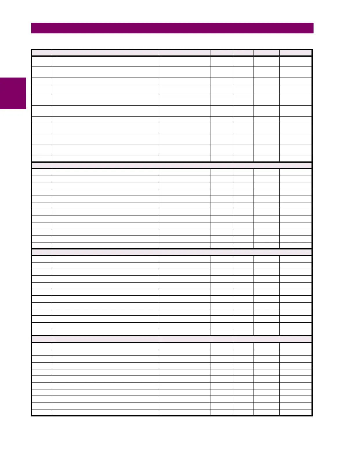
7EAB AG Loop Reactance -2147483647 to
2147483647
ohm 1 F060 0
7EAD AG Loop Impedance Magnitude 0 to 2147483647 ohm 1 F060 0
7EAF AG Loop Impedance Angle -359.9 to 0 degrees 0.1 F002 0
7EB0 BG Loop Resistance -2147483647 to
2147483647
ohm 1 F060 0
7EB2 BG Loop Reactance -2147483647 to
2147483647
ohm 1 F060 0
7EB4 BG Loop Impedance Magnitude 0 to 2147483647 ohm 1 F060 0
7EB6 BG Loop Impedance Angle -359.9 to 0 degrees 0.1 F002 0
7EB7 CG Loop Resistance -2147483647 to
2147483647
ohm 1 F060 0
7EB9 CG Loop Reactance -2147483647 to
2147483647
ohm 1 F060 0
7EBB CG Loop Impedance Magnitude 0 to 2147483647 ohm 1 F060 0
7EBD CG Loop Impedance Angle -359.9 to 0 degrees 0.1 F002 0
Neutral Overvoltage (Read/Write Grouped Setting) (3 Modules)
7F00 Neutral Overvoltage 1 Function 0 to 1 --- 1 F102 0 (Disabled)
7F01 Neutral Overvoltage 1 Signal Source 0 to 5 --- 1 F167 0 (SRC 1)
7F02 Neutral Overvoltage 1 Pickup 0 to 3.00 pu 0.001 F001 300
7F03 Neutral Overvoltage 1 Pickup Delay 0 to 600 s 0.01 F001 100
7F04 Neutral Overvoltage 1 Reset Delay 0 to 600 s 0.01 F001 100
7F05 Neutral Overvoltage 1 Block 0 to 4294967295 --- 1 F300 0
7F07 Neutral Overvoltage 1 Target 0 to 2 --- 1 F109 0 (Self-reset)
7F08 Neutral Overvoltage 1 Events 0 to 1 --- 1 F102 0 (Disabled)
7F09 Neutral Overvoltage 1 Curves 0 to 3 --- 1 F116 0 (Definite Time)
7F0A Reserved (8 items) 0 to 65535 --- 1 F001 0
7F11 ...Repeated for Neutral Overvoltage 2
7F22 ...Repeated for Neutral Overvoltage 3
Auxiliary Undervoltage (Read/Write Grouped Setting) (3 Modules)
7F60 Auxiliary Undervoltage 1 Function 0 to 1 --- 1 F102 0 (Disabled)
7F61 Auxiliary Undervoltage 1 Signal Source 0 to 5 --- 1 F167 0 (SRC 1)
7F62 Auxiliary Undervoltage 1 Pickup 0 to 3 pu 0.001 F001 700
7F63 Auxiliary Undervoltage 1 Delay 0 to 600 s 0.01 F001 100
7F64 Auxiliary Undervoltage 1 Curve 0 to 1 --- 1 F111 0 (Definite Time)
7F65 Auxiliary Undervoltage 1 Minimum Voltage 0 to 3 pu 0.001 F001 100
7F66 Auxiliary Undervoltage 1 Block 0 to 4294967295 --- 1 F300 0
7F68 Auxiliary Undervoltage 1 Target 0 to 2 --- 1 F109 0 (Self-reset)
7F69 Auxiliary Undervoltage 1 Events 0 to 1 --- 1 F102 0 (Disabled)
7F6A Reserved (7 items) 0 to 65535 --- 1 F001 0
7F71 ...Repeated for Auxiliary Undervoltage 2
7F82 ...Repeated for Auxiliary Undervoltage 3
Auxiliary Overvoltage (Read/Write Grouped Setting) (3 Modules)
7FA0 Auxiliary Overvoltage 1 Function 0 to 1 --- 1 F102 0 (Disabled)
7FA1 Auxiliary Overvoltage 1 Signal Source 0 to 5 --- 1 F167 0 (SRC 1)
7FA2 Auxiliary Overvoltage 1 Pickup 0 to 3 pu 0.001 F001 300
7FA3 Auxiliary Overvoltage 1 Pickup Delay 0 to 600 s 0.01 F001 100
7FA4 Auxiliary Overvoltage 1 Reset Delay 0 to 600 s 0.01 F001 100
7FA5 Auxiliary Overvoltage 1 Block 0 to 4294967295 --- 1 F300 0
7FA7 Auxiliary Overvoltage 1 Target 0 to 2 --- 1 F109 0 (Self-reset)
7FA8 Auxiliary Overvoltage 1 Events 0 to 1 --- 1 F102 0 (Disabled)
7FA9 Reserved (8 items) 0 to 65535 --- 1 F001 0
7FB1 ...Repeated for Auxiliary Overvoltage 2
7FC2 ...Repeated for Auxiliary Overvoltage 3
Table B–10: MODBUS MEMORY MAP (Sheet 42 of 74)
ADDR REGISTER NAME RANGE UNITS STEP FORMAT DEFAULT