Installation and Commissioning
Pneumatic Connections
24
Operating Instructions · VARIVENT
®
Vacuum Valve V
Edition 2016-06-30
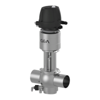
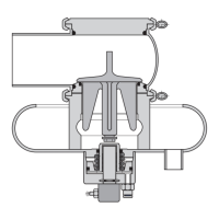
Valve with Welding Ends
This section describes the welding procedure for the valve.
Seals are wearing parts
Old seals will cause malfunction of the valve.
When fitting the valve be sure to fit new housing O-rings.
Carry out the following steps:
1. Disassemble the valve, see chapter “Disassembling the Valve“ (Page 30).
2. Fit the housing without sealing rings.
3. Fit the housing into place and tack it.
4. Always close the housing before welding.
5. Flush the housing with forming gas from the inside to push the oxygen out of the
system.
6. Weld the housing into the pipe system; use welding filler if necessary. Use the TIG
welding with pulse method.
7. Passivate the seam after welding.
8. Fit the seals.
9. Assemble the valve.
Done
Pneumatic Connections
To ensure reliable operation, the compressed air hoses must be cut exactly square.
Tools required: A hose cutter.
Carry out the following steps:
1. Shut off the compressed air supply.
2. Use the hose cutter to cut the pneumatic hoses square.
3. Push the air hose into the screw connection of the lifting actuator.
4. Re-open the compressed air supply.
Done
 Loading...