ADV200 • Appendix 303
SubCode Index SubIndex Notes
52 0x1803 1 TPDO4 enable
During the control phase, the system sends a HeartBeat message to the slave every 100 ms and checks the
Op state via HeartBeat producer message sent by the device, which must arrive within the time set in object
1017. If an error occurs it returns to Init .
If HeartBeat is not available and NodeGuarding is active instead, the timeout values set in objects 100C and
100D are used.
Among the objects requested during the conguration phase are those which contain the mapping, the mean-
ing of the data in the PDOs. The objects the slave may have mapped in the PDOs are a subset of those de-
ned by the DS401 prole. In particular, the list indicates objects recognised by the drive:
• 6000h Read Input 8 bit
• 6100h ReadInput 16 bit
• 6120h ReadInput 32 bit
• 6200h Write Output 8 bit
• 6300h WriteOutput 16 bit
• 6320h WriteOutput 32 bit
• 6400h ReadAnalog 8 bit
• 6401h ReadAnalog 16 bit
• 6411h WriteAnalog 16 bit
The conguration does not fail if other objects are detected, however the object in the PDO is not managed
when received and is written as 0 for transmission.
The objects are associated with the analog and digital input and output parameters in the order they are de-
tected.
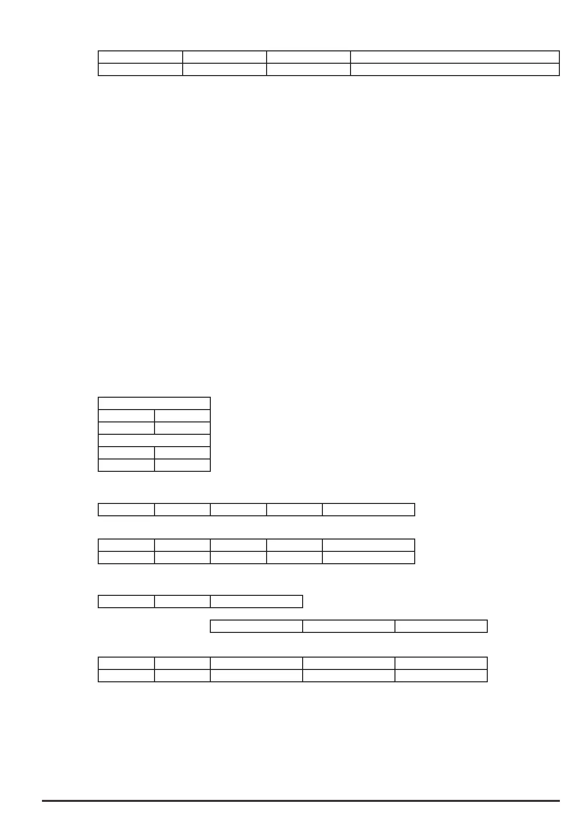
For example, if the slave is congured as follows
1600
1 6200h
2 6200h
1601
1 6300h
2 6300h
The data sent via RPDO will be associated in this order
Byte 0 Byte1 Byte2 Byte3 Digital out 0Ext mon
|
V
|
V
Byte 0 Byte1 Byte2 Byte3 PDO1
6200h 6200h -- --
Byte 0 Byte1 Digital out 0Ext mon
|
|
V
|
|
V
Byte 0 Byte1 Digital out 1Ext mon
|
V
|
V
Byte 0 Byte1 Byte2 Byte3 PDO1
6200h 6200h -- --
Following the transition to Op, the drive software reads and writes the PDOs (RPDO) and moves the data to
the I/O control blocks and periodically sends the Sync message.
Since there are only 2 devices in the network and data exchange is predened, synchronous PDOs are always
used to have repeatability in communication.
Data are exchanged in communciation cycles, the duration of which is predened with parameter 5488 “Ex-
ternal IO period” (available in the service menu and via the .sco conguration le). The default communication
cycle value is 8 ms.