ADV200 • Functions description and parameters list 63
14 – ANALOG INPUTS
Menu PAR Description UM Type FB BIT Def Min Max Acc Mod
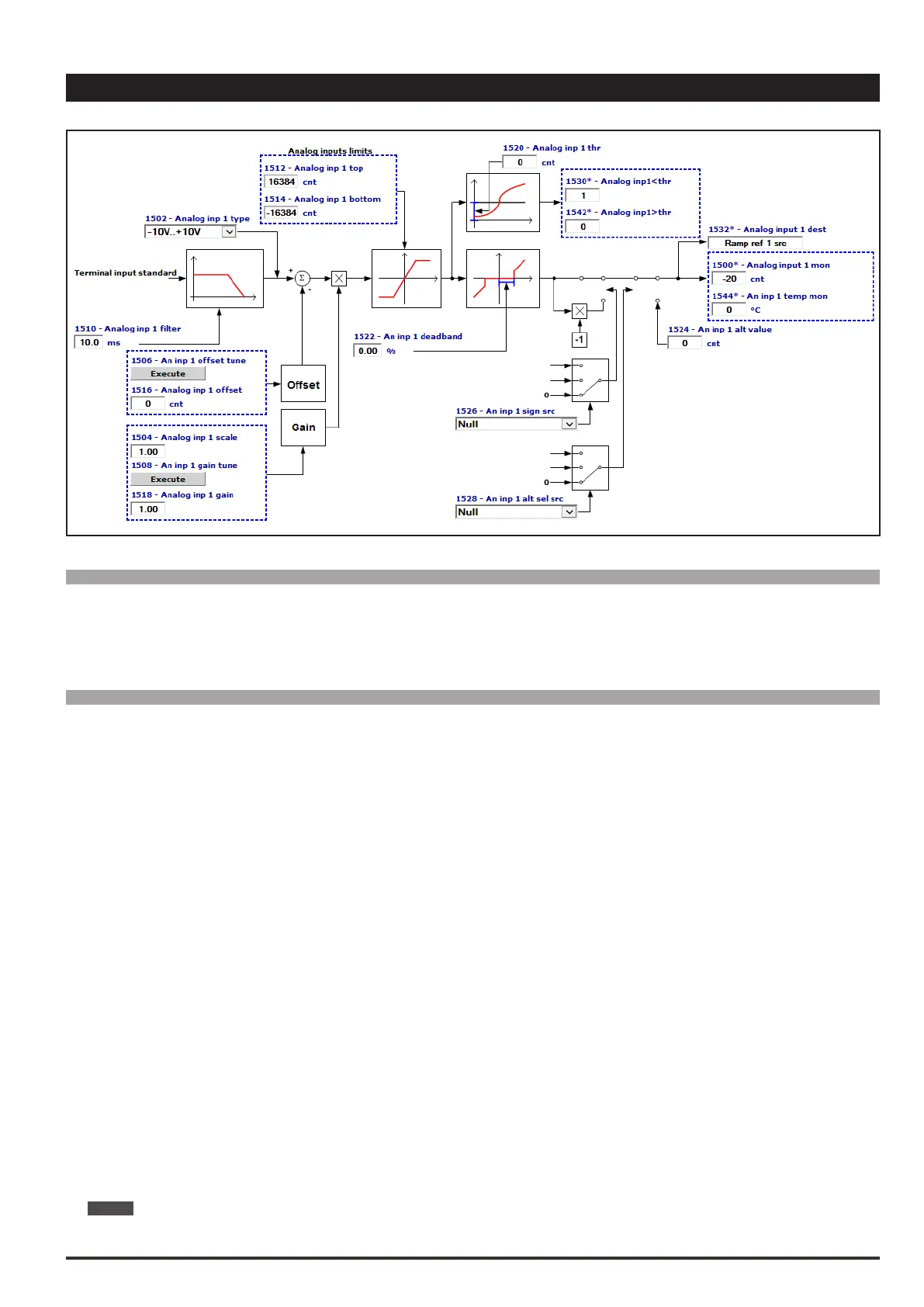
14.1 1500 Analog input 1 mon cnt INT16 16/32 0 0 0 R FVS
14.17 1550 Analog input 2 mon cnt INT16 16/32 0 0 0 R FVS
The value of the voltage on the output of the function block of the relative analog input is displayed.
Menu PAR Description UM Type FB BIT Def Min Max Acc Mod
14.2 1502 Analog inp 1 type ENUM -10V..+10V 0 2 RW FVS
14.18 1552 Analog inp 2 type ENUM -10V..+10V 0 2 RW FVS
Selection of the type of input (voltage or current). Depending on the input signal, move the switches on the
regulation card. The factory parameter is inputs set for differential voltage signals (± 10V).
0 -10V…+10V
1 0,20mA … 10V
2 4..20mA
3 0.1V..10.1V
4 KTY84
Select option 0 in order to connect a maximum voltage of ±12.5V (typically ±10V/5mA) to the analog input con-
cerned. If the signal is used as a reference, reverse the direction of rotation by inverting the voltage polarity.
With this selection, the analog input can acquire the temperature of motor with KTY84 / PTC sensor. (An
analog output need to be used as power supply signal).
Additional info are available through the Quick startup manual.
Select option 1 to connect a max voltage of 12.5V (typically 10V/5mA) or a signal in current from 0 ... 20 mA to
the analog input concerned. The signal must be positive.
Select option 2 to connect a current signal of 4...20 mA to the analog input concerned. The signal must be positive.
Select option 3 to connect 0.1V...10.1V to the analog input in use. You can also detect signal loss (due to dis-
connection or short circuit) with alarm [62] AnalogInpLoss.
Select option 4 to connect a KTY84 temperature sensor to the analog input in use (you have to use an analog
output as power supply signal). You can also detect signal loss (due to disconnection or short circuit) with
alarm [62] AnalogInpLoss.
NOTE! See chapter 7.2 of Quick startup manual for setting as reaading of a temperature sensor.