Ch.455
—————— Installation guidelines ——————
4.3. INSTALLATION MOUNTING CLEARANCE
NOTE! The dimensions and weights specifed in this manual should be taken into consideration
when the device is mounted. The technical equipment required (carriage or crane for large
weights) should be used. Improper handling and the use of unsuitable tools may cause
damage.
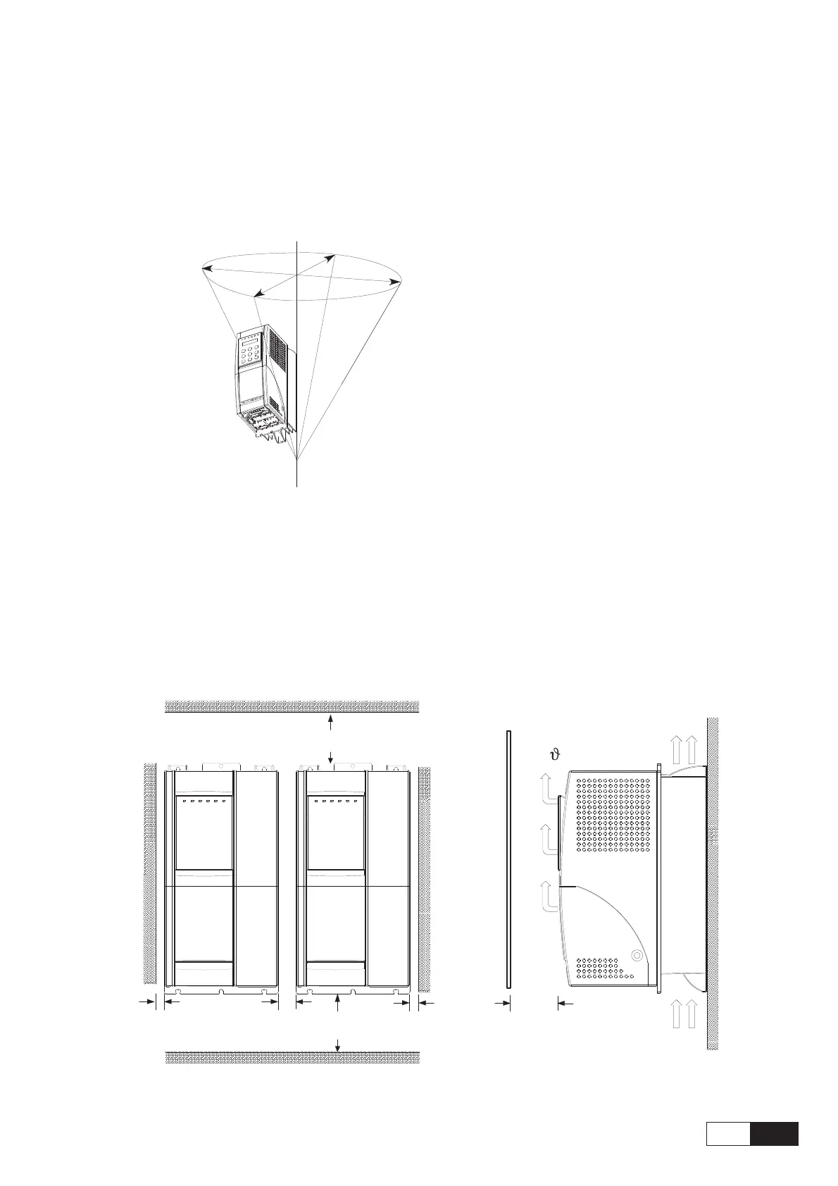
Figure 4.3.1: Max. Angle of Inclination
The maximum angle of inclination is 30°
NOTE! The Drives must be mounted in such a way that the free flow of air is ensured. The
clearance to the device must be at least 150 mm (6 inches). A space of at least 50 mm (2
inches) must be ensured at the front.
From size 81600 the top and bottom clearance must be at least 380 mm (15 inches), on
front and sides must be ensured a space of at least 140 mm (5.5 inches).
Devices that generate a large amount of heat must not be mounted in the direct vicinity
of the frequency inverter.
Figure 4.3.2: Mounting Clearance
³
10 mm 0.4"()
[140mm (5.5")]
³
6"150 mm ()
[380mm (15")]
³
2" )50 mm (
[140mm (5.5)]
³
20 mm (0.8")
[140mm (5.5")]
³
6"150 mm ()
[380mm (15")]
³
10 mm 0.4"()
[140mm (5.5")]
[...] For 81600 size (and higher)
NOTE! Fastening screws should be re-tightened after a few days of operation.