Ch.573
—————— Wiring procedure ——————
- only shielded cables are used
- power cables and control cables for contactors/relays are routed separately
NOTE! See the manual “SLINK3 Communication protocol” for more detail.
5.4.2. RS 485 Serial Interface Connector Description
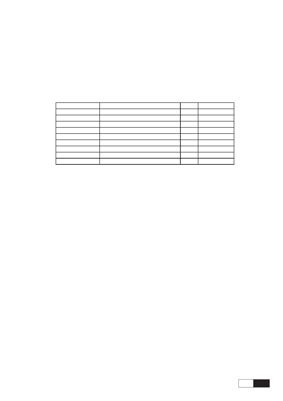
Table 5.4.2.1: Assignment of the plug XS connector for the RS 485 serial interface
Designation Function I/O Elec. Interface
PIN1 Internal use ––
PIN2 Internal use ––
PIN3 RxA/TxA I/ORS485
PIN 4 Internal use ––
PIN5 0V (Ground for 5 V) – Power supply
PIN6 Internal use ––
PIN 7 RxB/TxB I/ORS485
PIN8 Internal use ––
PIN9 +5V – Power supply
ai4110
I = Input O = Output