Ch.567
—————— Wiring procedure ——————
5.3. REGULATION SECTION
5.3.1 RV33 Regulation Card
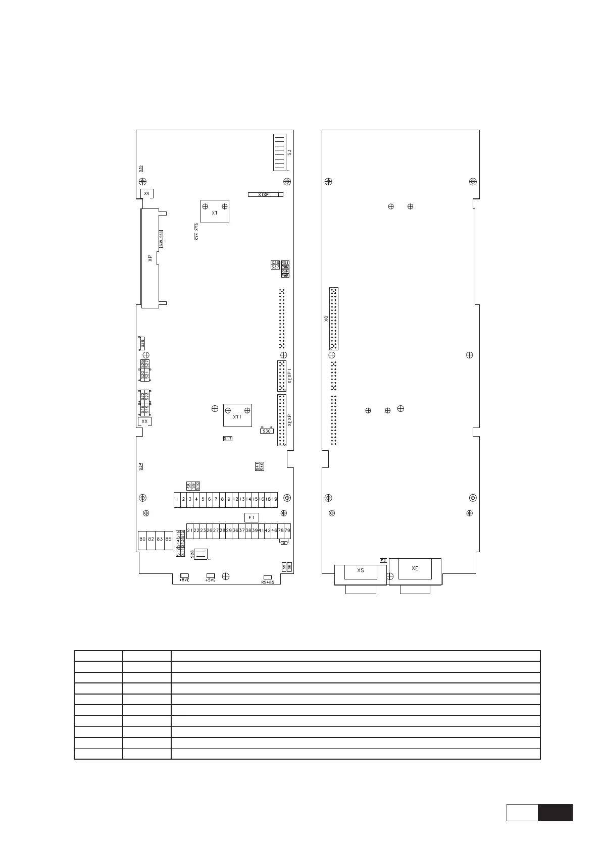
Figure 5.3.1.1: RV33-4 Regulation Card Switch & Jumpers
FRONT SIDE BACK SIDE
Table 5.3.1.1: LEDs & Test points on Regulation card
Designation Color Function
RST red LED lit during the Hardware Reset
PWR green LED lit when the voltage +5V is present and at correct level
RS485 green LED is lit when RS485 interface is supplied
PWM green LED lit during IGBT modulation
RUN green LED is flashing when regulation is running (not in STARTUP menu)
+5VE green LED lit when encoder power supply +5V (XE-9)
+8VE red LED lit when encoder power supply +8V (XE-2)
XY4 (test point) Phase current signal (U) (see manual "AVy Function description and parameters", table 1.3.1.2.2)
XY5 (test point) Reference point
ai4050