AVy - HGB
Ch.5 84
Resistor model: MRI/T600 100R
Nominal power P
NBR
= 600 [W]
Maximum energy E
BR
= 22 [kJ]
Inverter mains supply = 460V
From table 5.8.2.2: V
BR
=780V
T
BRL
=
2
E
BR
P
PBR
=
24000
6084
=
7.8[s]2
P
PBR
=
V
BR
R
BR
2
=
780
100
2
= 6084 [W]
It is necessary to consider the following relation:
A) If T
BR
≤≤
≤≤
≤ E
BR
/ P
PBR
verify:
1) P
MB
≤≤
≤≤
≤ 2 . E
BR
/ T
BR
Where: P
MB
is the average power of the cycle (see.fig. 5.8.2.3)
2)
P.
MB
T
BR
2T
C
£ P
NBR
The average power of the cycle must not be higher than the nominal power of the resistor.
B) If T
BR
>>
>>
> E
BR
/ P
PBR
that is to say, in case of very long braking time, it must be dimensioned P
MB
≤ ≤
≤ ≤
≤ P
NBR
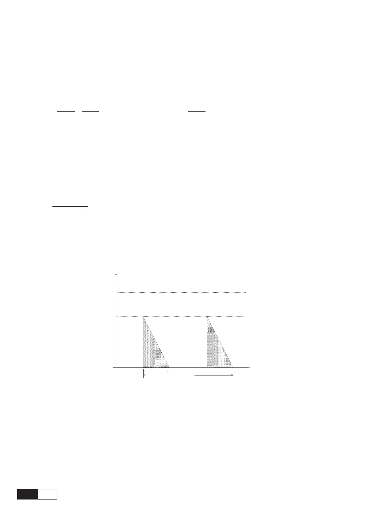
Figure 5.8.2.3:Generic braking cycle with triangular profile
T
C
n,P
P
PBR
T
BR
t
P
MB
If one of the above mentioned rules is not respected, it is necessary to increase the nominal power of the
resistor, respecting the limit of the internal braking unit (reported in table 5.8.2.3),
In order to protect these resistors from dangerous overload, the parameters BU ovld time and BU duty
cycle (menu FUNCTIONS\Brake unit) manage maximum time and duty cycle at which the resistors can
tollerate their peak power P
PBR.
The data must be related to the AC mains for which they are specified defined by the parameter
BU DC vlt (menu FUNCTIONS\Brake unit).
The default parameters are calculated for a braking threshold that correspond to a Mains voltage = 400V.