Ch.583
—————— Wiring procedure ——————
T
CL
Minimum cycle time in condition of limit operating cycle (braking power = P
PBR
with typical triangular profile)
T=
CL
T
BRL
P
PBR
P
NBR
=[s]
1
2
The BU overload alarm occurs if the duty cycle exceeds the maximum data allowed in order to prevent
possible damages to the resistor.
Resistor model: Standard resistor data
Example code: MRI/T900 68R
MRI = resistor type
900 = nominal power (900 W)
T= with safety thermostat
68R = resistor value (68 Ω)
NOTE! The suggested match of resistor-model and inverter-size, allows a braking stop at nominal
torque with duty cycle T
BR
/ T
C
= 20%
Where: T
BR
= Braking time
T
C
= Cycle time
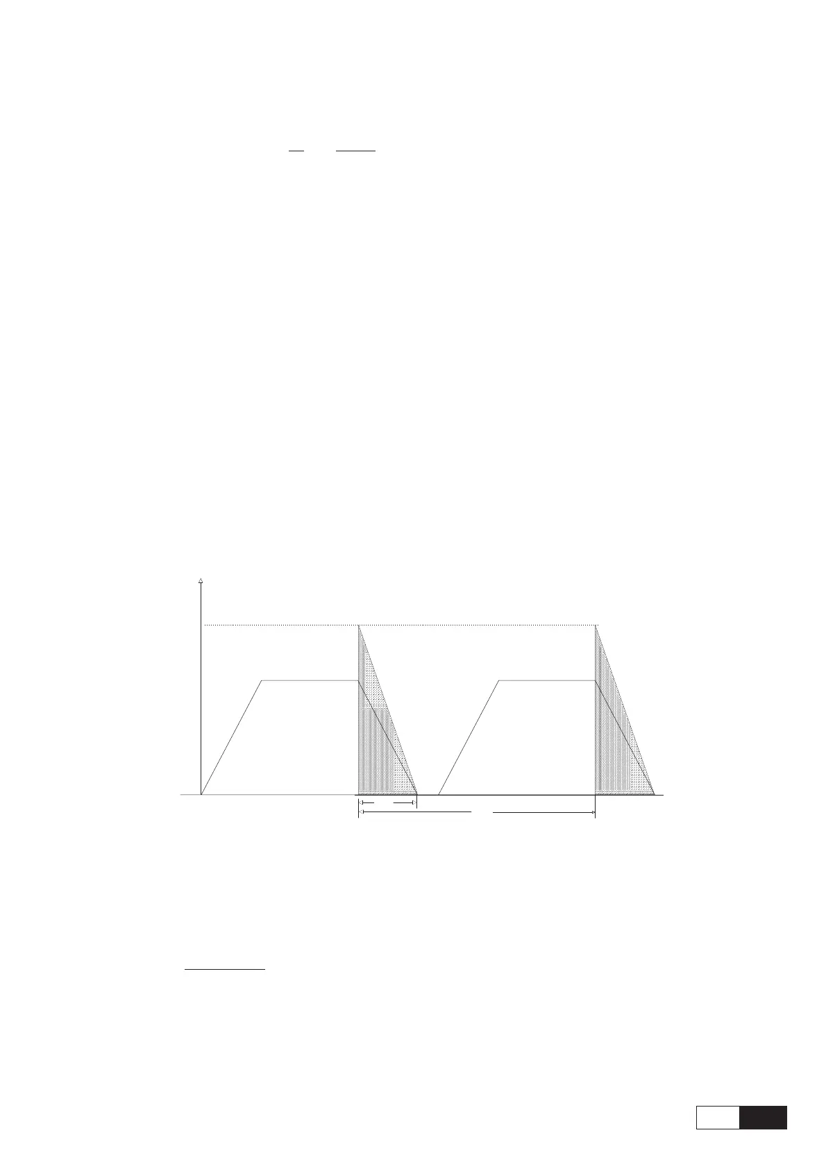
Figure 5.8.2.2: Braking cycle with T
BR
/ T
C
= 20%
T
C
P, n
T
BR
n
t
The standard resistor can be used for couplings, different from the ones above reported.
These resistors, whose technical data are reported in the table 5.8.2.1, have been dimensioned to tolerate an
overload equal to 4 time their nominal power for 10 seconds.
In any event they can tolerate also an overload, whose energetic dissipation was the same of the maximum
power level defined by:
P=
PBR
V [V]
BR
2
R [ohm]
BR
=[w]
Where: V
BR
= braking unit threshold (see table 5.8.2.2)
With reference to the figure 5.8.2.4, where the power profile is the typical triangular one, the following
example can be taken into consideration (see also table 5.8.2.1).