45 / 68
651
G Screw the diaphragm valve body into the
piping, use appropriate thread sealant.
The thread sealant is not included in the
scope of delivery.
Observe appropriate regulations for
connections!
After the installation:
G Reactivate all safety and protective
devices.
10.2 Control functions
The following control functions are available:
Control function 1
Normally closed (NC):
Valve resting position: closed by
spring force. Activation of the actuator
(connector 1) opens the valve. When the
actuator is vented, the valve is closed by
spring force.
Control function 2
Normally open (NO):
Valve resting position: opened by
spring force. Activation of the actuator
(connector 1) closes the valve. When the
actuator is vented, the valve is opened by
spring force.
10.3 Connecting the
control medium
Important:
Connect the control medium lines
tension-free and without any bends
or knots!
Use appropriate connector accord-
ing to the application.
Thread size of the control medium
connectors: M5
The control medium connector is available
positioned in-line with flow direction (code T)
and 90° offset (code R). Other connectors
only serve for venting.
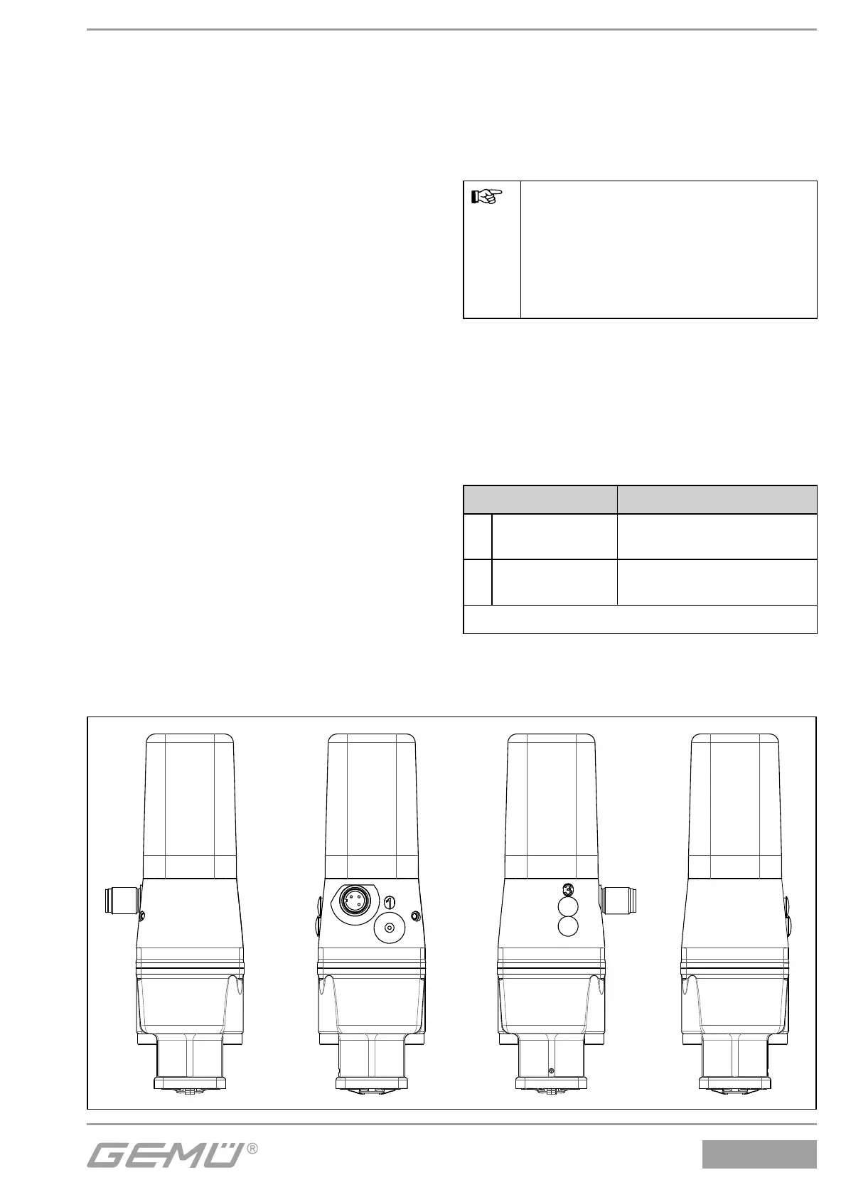
Control function Connector
1
Normally closed
(NC)
1: Control medium (open)
3/5: Vent hole
2
Normally open
(NO)
1: Control medium (close)
3: Vent hole
For connectors see pictures below and pages 46-49
Combi switchbox / Actuator size 0 / Control function 1