25 / 68
651
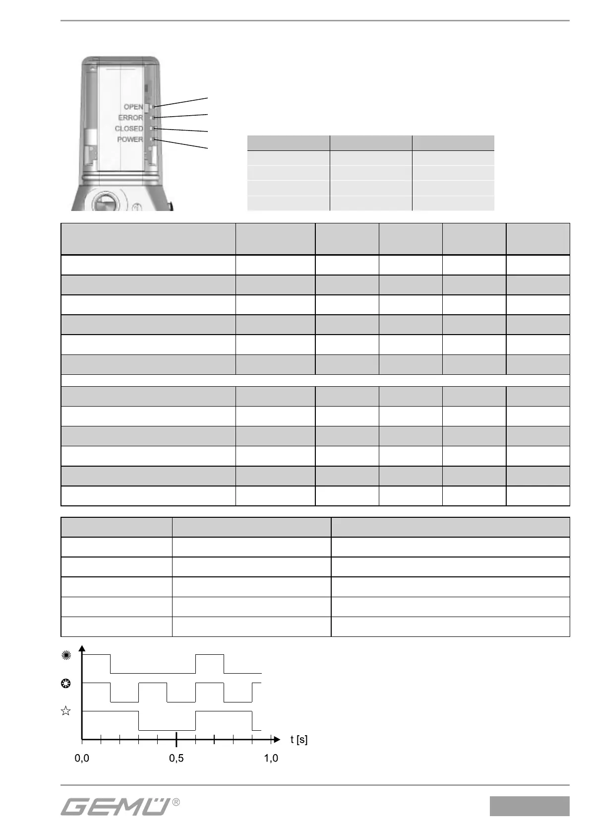
15.3 Optische Anzeige
1
2
3
4
LED Bezeichnung Farbe
1 OPEN gelb
2 ERROR rot
3 CLOSED orange
4 POWER gelb
Bedeutung Fehlernummer
LED 1
OPEN
LED 2
ERROR
LED 3
CLOSED
LED 4
POWER
Position erreicht -
HHHG
Ventil in Endlage AUF -
GHHG
Ventil in Endlage ZU -
HHGG
Ventil fährt in Richtung AUF -
$HHG
Ventil fährt in Richtung ZU -
HH$G
Regler in Initialisierungsphase -
$H$G
Sollwert > 20,5 mA / 10,25 V Fehler Nr. 1
$=HG
Sollwert < 3,5 mA Fehler Nr. 2
H=$G
Regler nicht initialisiert Fehler Nr. 3
$=$G
Regler nicht kalibriert Fehler Nr. 4
GGG$
Gerätefehler Fehler Nr. 5
H=HG
Regler arbeitet mit geringer Güte Warnung Nr. 1
5G
Legende LED Zustand Blinkfrequenz
H
LED aus
G
LED an
5
LED blinkt kurz auf f = 1,66 Hz; 0,15 s an / 0,45 s aus
=
LED blinkt schnell f = 3,33 Hz; 0,15 s an / 0,15 s aus
$
LED blinkt langsam f = 1,66 Hz; 0,30 s an / 0,30 s aus
 Loading...


