26 / 68
651
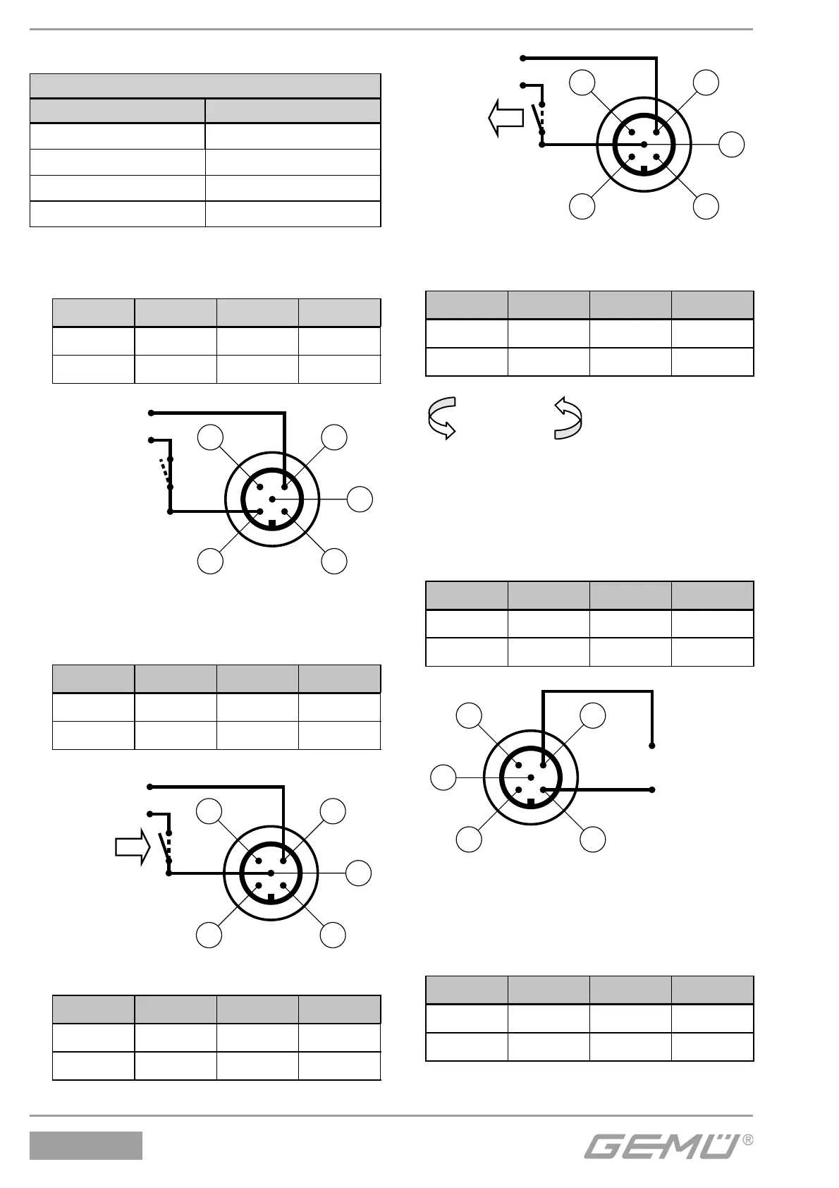
15.4 Automatische Initialisierung
Legende
LED Symbol
Aus
H
An
G
Blinkt schnell
=
Blinkt langsam
$
1. Versorgungsspannung 24 V einschalten.
POWER LED leuchtet.
LED Symbol LED Symbol
OPEN
$
CLOSED
$
ERROR
=
POWER
G
GND
+24V DC
43
12
5
2. Initialisierungsspannung 24 V DC
an Pin 5 anschließen und aktivieren
(t > 100ms).
LED Symbol LED Symbol
OPEN
$
CLOSED
$
ERROR
=
POWER
G
GND
+24V DC
43
12
5
3. Initialisierungsspannung deaktivieren.
LED Symbol LED Symbol
OPEN
$
CLOSED
$
ERROR
H
POWER
G
GND
+24V DC
43
12
5
4. Die automatische Initialisierung wird
durchgeführt.
LED Symbol LED Symbol
OPEN
$
CLOSED
$
ERROR
H
POWER
G
Initialisierung
15.5 Inbetriebnahme
1. Analogen Sollwert 4-20 mA
(0-20 mA / 0-10 V) vorgeben.
LED Symbol LED Symbol
OPEN
H
CLOSED
H
ERROR
H
POWER
G
GND
43
12
5
+4-20mA
2. Nach Beenden der Initialisierung wird
das Prozessventil in die Position gemäß
Sollwertsignal positioniert.
Sollwert min
LED Symbol LED Symbol
OPEN
H
CLOSED
G
ERROR
H
POWER
G