8 Owner’s Manual for Snow Blower
General Information and Setup
2. Contact Generac Customer Service at 1-888-436-
3722 (1-888-GENERAC), or www.generac.com
with the unit model and serial number for any miss-
ing carton contents.
3. Recor
d model, serial number, and date of pur-
chase on front cover of this manual.
Assembly Instructions
Proceed as follows to assemble unit:
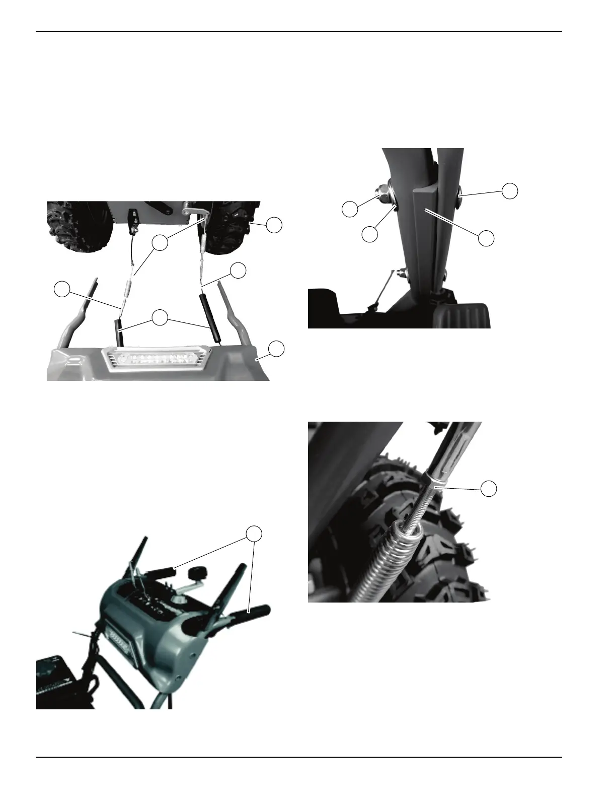
1. See Figure 2-5. Position handlebar assembly (A)
behind snow blower (B) in a flat, clean area.
Figure 2-5. Handlebar Assembly
2. Mo
ve plastic covers (C) away from cable spring
hooks (D).
3. Atta
ch cable spring hook of drive control cable (E)
into pulley wire on left side of unit.
4. Atta
ch spring hook of auger control cable (F) into
the tension connector on right side of unit.
5. See Figure 2-6. Have a helper hold upper handle-
bar assembly in position on lower handlebar (G).
Figure 2-6. Upper and Lower Handlebar Assembly
6. See Figure 2-7. Place adaptor plates (H) between
upper and lower handlebar assemblies and secure
with
M8 X 55 bolts, 8 X 22 X 2 washers (J) and M8
jam nuts (K) using a 13mm wrench.
NOTE: V
erify bolt heads are on the outside of the han-
dlebar and the square portion of the bolts go fully into the
sq
uares in the handlebar.
Figure 2-7. Adaptor Plate Assembly
7. See Figure 2-8. Lift plastic covers and inspect jam
nuts (L) on auger control cable and drive control
cabl
e to verify tightness. Tighten as needed using
a 6mm wrench to hold the cable and an 8mm
wrench to tighten the jam nut.
Figure 2-8. Control Cable Jam Nut

 Loading...