Owner’s Manual for Snow Blower 9
General Information and Setup
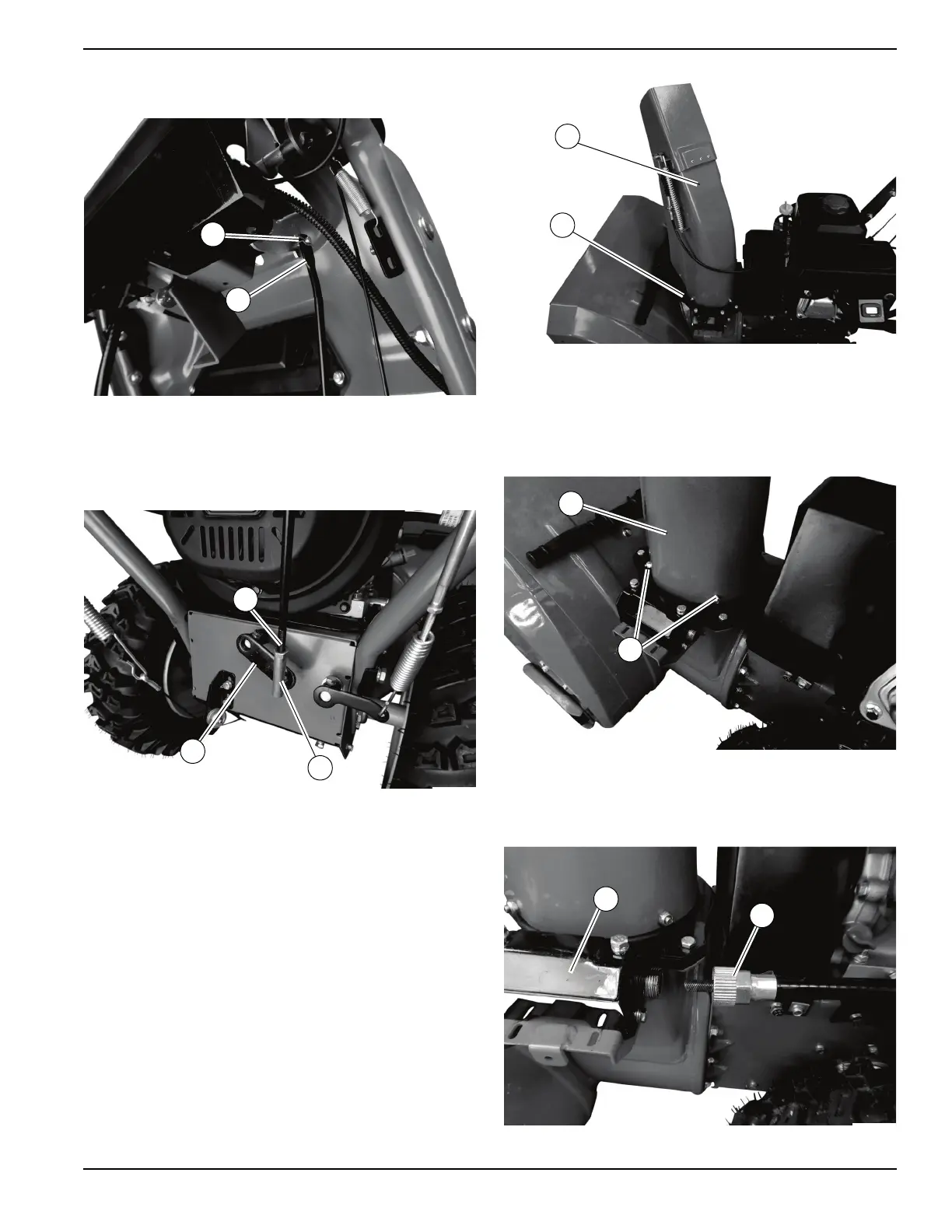
8. See Figure 2-9. Remove pin (M) and install upper
end of shift connection bar (N).
Figure 2-9. Upper End Shift Connection Bar
9. See Figure 2-10. Remove locknut from lower
gim-
bal (O) of shift connector bar (P) and insert threads
th
rough shift connector (Q).
Figure 2-10. Lower Gimbal of Shift Connector Bar
10. Se
cure gimbal with locknut using an 11mm wrench
on the gimbal and a 13mm wrench on the locknut.
11. V
erify gimbal upper jam nut is tight using a 14mm
wrench.
12. See Figure 2-11. Place chute assembly (R) onto
gear plate assembly (S) and align mounting holes.
Figure 2-11. Chute Assembly
13. See Figure 2-12. Secure chute assembly (T) to
gear plate assembly (U) with three M8-1.25 X
16
mm carriage bolts and locknuts using a 13mm
wrench.
Figure 2-12. Carriage Bolt Locations
14. See Figure 2-13. Screw end of rotation bracket
cable (W) onto rotation bracket (X).
Figure 2-13. Rotation Bracket Cable

 Loading...