10 Owner’s Manual for Snow Blower
General Information and Setup
NOTE: It may be necessary to turn chute rotation handle
on control panel to align the cable end with the worm
gear in the bracket.
15. See Figure 2-14. Place rotation bracket cable (Y)
into connecting plate (Z).
Figure 2-14. Rotation Bracket Cable
16. See Figure 2-15. Install eyelet end (A) of deflector
cable (B) onto deflector lever (C) and secure with
p
in (D).
Figure 2-15. Deflector Cable Installation
17. L
oosen top jam nut (E), slide threaded portion of
deflector cable into bracket (F) and tighten two jam
nuts against bracket using two 13mm wrenches.
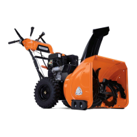
18. See Figure 2-16. Screw handles (G) onto shift and
deflector levers, and tighten jam nuts (H) using a
17
mm wrench.
Figure 2-16. Lever Handles Installation
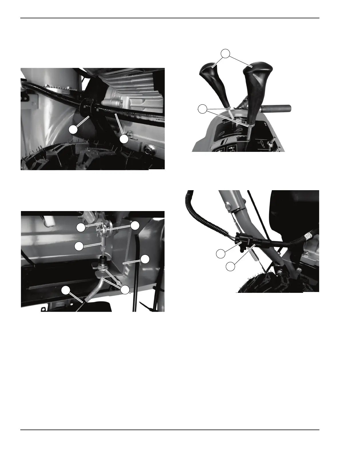
19. See Figure 2-17. Use wire cutters to cut cable tie
securing heated grip connector (I) and insert
he
ated grip connector into harness plug (J).
Figure 2-17. Heated Grip Connector
 Loading...