Owner’s Manual for Snow Blower 23
Maintenance
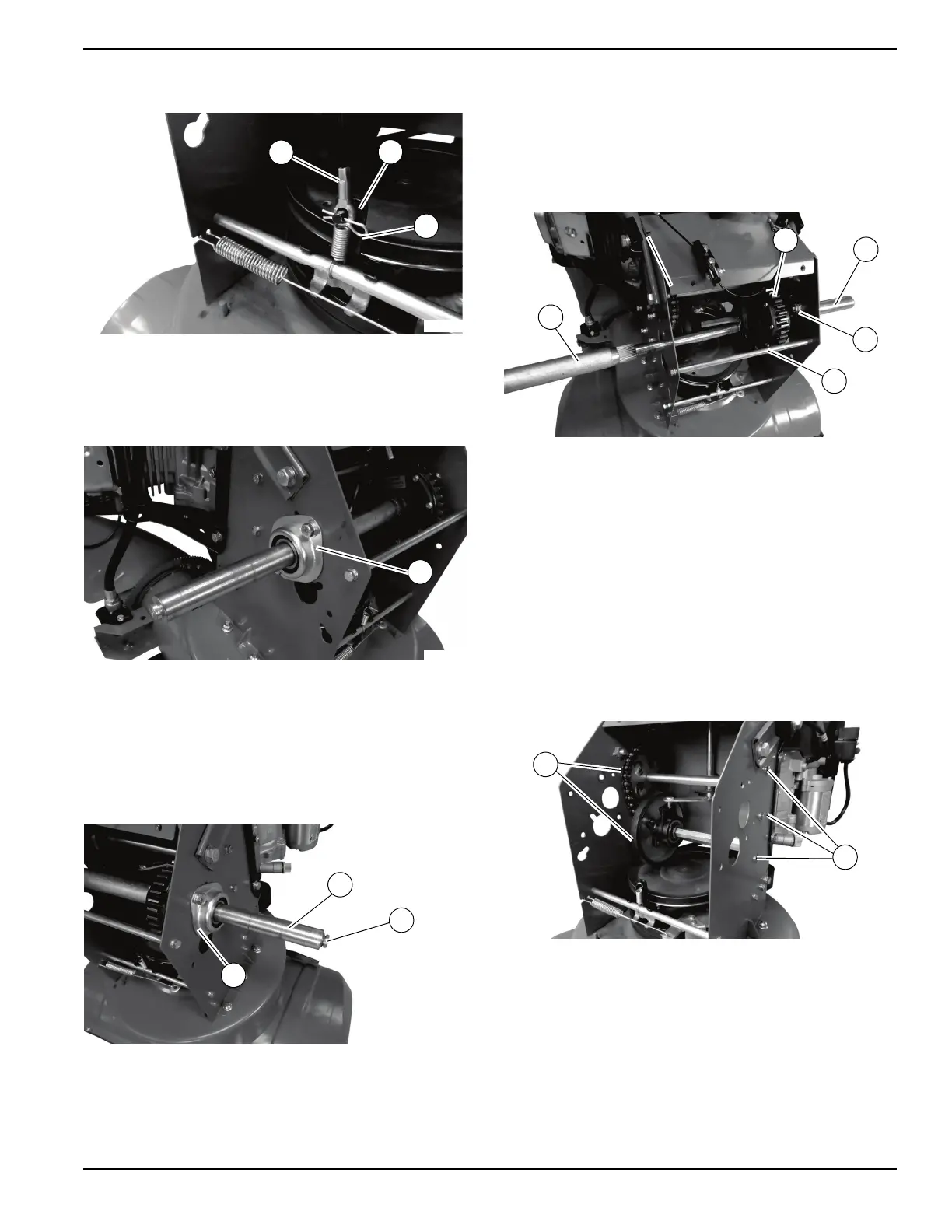
8. See Figure 4-23. Remove pin (I) and traction cable
(K) from traction drive bracket (J).
Figure 4-23. Removing Pin and Traction Cable
9. See Figure 4-24. Remove the two bolts, lock
washers, flat washers, and l
ocknuts securing left
side wheel bearing assembly (L) using two 13mm
wrenches.
Figure 4-24. Wheel Bearing Assembly
10. Remove bearing assembly
from axle.
11. See Figure 4-25. Hold the larger diameter outer
shaft (M) of the right-side axle shaft while hitting
the
smaller diameter inner shaft (N) with a dead
blow hammer. This will push the smaller shaft in,
separating it from the larger outer shaft.
Figure 4-25. Outer and Inner Shafts
NOTE: A
brass punch may be needed to push the
smaller diameter shaft in further to separate the two shaft
sections.
12. R
emove the two bolts, lock washers, flat washers,
and locknuts securing right side wheel bearing
assembly (O) using two 13mm wrenches. Remove
the bearing assembly from the axle.
13. See Figure 4-26. Remove the two rear strut bolts
and lock washers using a 10mm wrench and
re
move strut (P).
Figure 4-26. Rear Strut Assembly
NOTE: V
erify the orientation of the differential (Q) on the
shaft before removing it (bolt heads facing left side of
machine), to keep it in the same orientation during
assembly.
14. Remo
ve the long shaft (T), short semi-shaft, shaft
sleeve (Q), and differential (S).
NOTE: A
dead blow hammer may be used to tap the dif-
ferential to separate it from the shaft splines for removal.
15. See Figure 4-27. Remove the six bolts, lock wash-
ers and flat washers (U) securing the friction drive
whe
el assembly (V) using a 10mm wrench.
Figure 4-27. Removing Friction Drive Wheel
Assembly
16. Carefully remove fric
tion wheel assembly. Verify
everything stays together.
NOTE: V
erify the chain side of the friction drive wheel
assembly stays together during the following steps for an
easier installation.
 Loading...