24 Owner’s Manual for Snow Blower
Maintenance
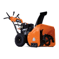
17. See Figure 19. Remove pin (W) from the hexagon
shaft (X).
Figure 4-28. Hexagon Shaft Pin
18. Hold
the two shafts in place and pull right side
bearing seat away from assembly.
19. Remove rubber wheel/shift b
earing assembly (Y)
from the hexagon shaft and remove the guide.
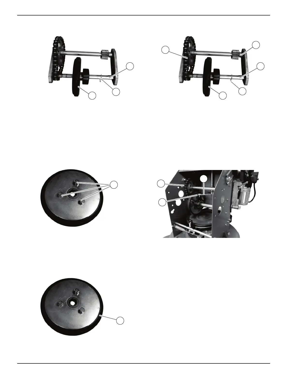
20. See Figure 4-29. Use a 10mm wrench to remove
the three bolts (Z) securing the rubber wheel to the
shift b
earing assembly and remove the rubber
wheel.
Figure 4-29. Friction Drive Wheel
Assembly
Proceed as follows to assemble the friction drive wheel:
1. See Figure 4-30. Install new rubber wheel (A) onto
shift bearing assembly in the orientation shown.
Figure 4-30. Friction Drive Wheel
2. See Figure 4. Slide rubber wheel/shift bearing
assembly (B) onto hexagon shaft (C).
Figure 4-31. Installing Shift Bearing Assembly on
Hexagon Shaft
NOTE: V
erify bolt heads are facing chain (D) and shift
bearing is facing away from the chain.
3. Position b
earing seat with bearings (E) onto the
shafts.
4. Insta
ll pin (F) into hexagon shaft.
5. See Figure 4-32. Install friction drive wheel assem-
bly (G) into unit.
Figure 4-32. Installing Friction Drive Wheel Assembly
NOTE: V
erify chain is on left side of unit and shift fork pin
(H) is inserted into shift bearing slot (I) when positioning
the friction drive wheel assembly into unit.
6. See Figure 4-33. Install long drive
shaft (J), short
drive shaft (K), shaft sleeve (L) and differential (M)
into the
machine. A dead blow hammer may be
needed to push longer shaft into shorter shaft.
 Loading...