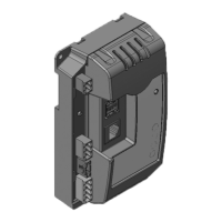
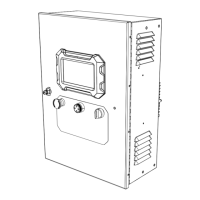
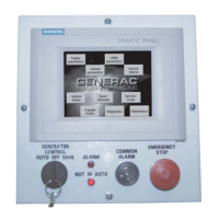
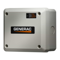
6 Owner’s Manual for Power Zone Pro Main Controller
General Information
Features
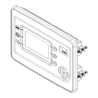
• HMI 4.3 inch Color Touchscreen Display
• System Configurable via the Connectivity server
using most Wi-Fi
®
, Bluetooth
®
devices, or wired
Ethernet connection
• Remote Communication via Modbus
®
RTU,
Modbus TCP/IP, 10/100 Mbs Ethernet IEEE 802.3
or Wi-Fi
• Configurable Analog and Digital I/O
• Configurable Monitoring of Analog I/O, Digital I/O,
and Machine State Data
• Configurable Detection and Mitigation of Faults
with E-Mail Annunciation
• Configurable Logging of Faults and Events with
Associated Data Capture
• Configurable Logging and Trending of Data
• Digitally Controlled Generator Output Voltage and
Frequency Regulation
• Customer Programmable Built-in Multichannel PLC
Logic Controller
• Alternator I
2
T with 300% Current Limiting for
Breaker Coordination
• Alternator Ground Fault Indication
Parameters Monitored on Display or
Connectivity Server
•
Keyswitch Position Monitoring
• Amps per Phase - Generator
• Line to Line and Line to Neutral Volts - Utility and
Generator
• Power Factor - Generator
• Real Power - kW - Generator
• Apparent Power - kVA - Generator
• Reactive Power - kVAR - Generator
• Frequency - Utility and Generator
• Engine Speed
• Engine Coolant Temperature
• Engine Oil Pressure
• Engine Oil Temperature
• Battery Voltage
• Shutdown Messages
• Diagnostics
• Maintenance Events/Information
• Engine Run Hours
Voltage Regulation (Single or Three-Phase
Module Options)
•
Digital Control
• Single-Phase or Three-Phase RMS Sensing with
Loss of Sensing Protection
• Variable V/F Slope Settings and Adjustable Gains
• Negative Power Protection
• Soft Start Ramping
• Fault Protection (I
2
T Function and GFI)
Electronic Governor
•
Electronic Speed Control for Electronically
Controlled Compression and Spark Ignited
Engines
• Adjustable Gains
• Low Speed Exercise
PLC (Built-In Programmable Logic Controller)
•
Configurable Through Software Tool
• Customer Configurable for Non-Standard Options
• Up to 8 Simultaneously Running PLC Programs or
in Sequence
Connections
•
21 Digital Outputs Maximum (Open Drain, 35 V
1.7 A)
• 7 fast PWM capable Outputs, 1 High Current
• 15 Digital Inputs Maximum
• 7 fast PWM capable Inputs
• 12 General Purpose Analog Inputs
• 2 Special Purpose Analog Inputs
• 2 Analog Outputs (0-10 V )
• 1 E-Stop Relay Output
• 3 Current Sense Inputs
• 8 High Voltage Sense Inputs (3-Phase + Neutral)
• 1 Magnetic Pickup Input
• 1 Coolant Level Sensor Input
• 2 CAN bus Channels
• 2 External RS-485 Ports (1 available to customer)
• 2 Switchable 12 V Power Outputs
NOTE: Actual I/O may vary due to configuration.
Qualification Testing
•
Life Test in Environmental Chamber
• Temperature Rating
• Vibration Tested and Protected
 Loading...
