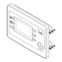
Owner’s Manual for Power Zone Pro Main Controller 1
Table of Contents
Section 1: Introduction and Safety
Introduction ..................................................................1
Read This Manual Thoroughly ....................................1
Safety Messages ..........................................................1
Safety Rules .................................................................2
General Hazards .........................................................2
Electrical Hazards ........................................................2
Section 2: General Information
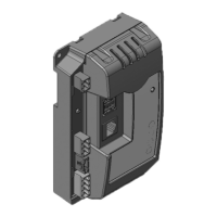
Equipment Description ................................................3
Symbol Definition ........................................................3
Acronyms .....................................................................3
Connections .................................................................4
Dimensions ...................................................................5
Features ........................................................................6
Parameters Monitored on Display or Connectivity
Server ..........................................................................6
Voltage Regulation (Single or Three-Phase Module
Options) .......................................................................6
Electronic Governor .....................................................6
PLC (Built-In Programmable Logic Controller) ............6
Connections ................................................................6
Qualification Testing ....................................................6
Codes and Standards ..................................................7
Protections ..................................................................7
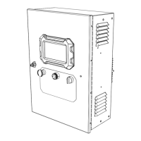
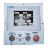
Control Panel and Touch Screen ................................7
Specifications ...............................................................8
Section 3: Installation and Operation
Mounting and Grounding ..........................................11
Cleaning ......................................................................11
Connections ...............................................................11
Power Supply ............................................................11
Connectivity Server Wiring ........................................11
Module CAN Bus Interface ........................................11
ECU CAN J1939 Interface .........................................11
CAN Bus and RS-485 Termination Resistor .............12
Module Power Supply Wiring ....................................12
Analog Sensor Power Supply Wiring .........................12
Digital Inputs (DI) .......................................................12
Digital Outputs (DO) ..................................................12
High Current Digital Output .......................................12
General Purpose Analog Inputs (GPAI) ....................12
Special Analog Inputs ................................................13
Oxygen Sensor Special Analog Input ........................13
Coolant Level Special Analog Input ..........................13
AC Voltage Sensing Inputs .......................................13
AC Current Sensing Inputs ........................................13
Analog Outputs ..........................................................14
RPM Sensor Input .....................................................14
Watchdog and Overspeed .........................................14
Voltage and Current Sense Input Calibration ............14
Pin Map .......................................................................15
Operation ....................................................................21
Standby Generator Operation ...................................21
Protections .................................................................21
Analog Sensor Failure ...............................................21
Overcurrent I2T ..........................................................21
Short Circuit ...............................................................22
Voltage Regulation (Single or Three-Phase
Module Options) .........................................................22
Built-In PLC (Programmable Logic Controller) .......22
I/O Configuration and Programming ........................22
Touchscreen Display .................................................22
Top Banner ................................................................23
Data Area ..................................................................23
Bottom Banner (Menu Buttons) .................................23
Bargraphs ..................................................................24
Alarm and Warning Icons ..........................................24
Date and Time Format ..............................................25
Units Format ..............................................................25
Screen Saver .............................................................25
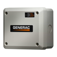
Connectivity Server ...................................................25
Power Zone Pro Menu Map .......................................26
Section 4: Troubleshooting
Troubleshooting Guide .............................................27
 Loading...
