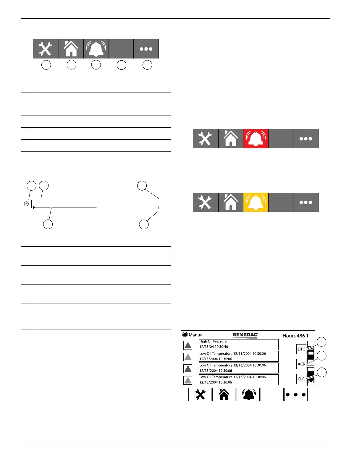
F
G
H
I
J
009400
24 Owner’s Manual for Power Zone Pro Main Controller
Installation and Operation
Figure 3-7. Second Set of Buttons
F Tools
G Home
H Display Alarms
I Blank (unused)
J More
Bargraphs
Engine Speed
1790
RPM
A
B
C
D
E
009401
Figure 3-8. Bargraph
A Icon - Representation of the parameter being
displayed.
B Title - Description of the measurement being
displayed.
C Value - Value of the parameter being displayed.
This reading is updated every 0.5 seconds.
D Bargraph - Magnitude of the value being
displayed. This reading is updated every 0.5
seconds.
E Units - Unit of measurement.
Alarm and Warning Icons
There are both alarms and warnings in the system (either
can be referred to as an “event”). To the display they
function the same, but bring up different colored icons:
red for an alarm, orange for a warning (see Figure 3-4,
items C and D). Both alarms and warnings can be active
at the same time.
If an alarm is active, it will be indicated by an alarm icon
in the top banner, flashing at a rate of once per second. If
a warning is active, it will be indicated by a warning icon
in the top banner, flashing at a rate of once per second.
If there is any alarm AND the bottom banner is displaying
the set of buttons containing the “Display Alarms” button,
then that button will be highlighted red and flashing at a
rate of once per second, as shown in Figure 3-9. If there
is any warning AND the bottom banner is displaying the
set of buttons containing the “Display Alarms” button,
then that button will be highlighted orange and flashing at
a rate of once per second, as shown in Figure 3-10.
If there are alarms and warnings both active, then alarms
take precedence and the button will flash red, as shown
in Figure 3-9.
If there are no alarms or warnings, the “Display Alarms”
button will return to its normal display.
009402
Figure 3-9. Alarm Button
009403
Figure 3-10. Warning Button
Press the “Display Alarms” button to change the screen
data area to a scrollable list of icons and text for up to
eight events.
See Figure 3-11. Press the “DTC” button (A) to display
the J1939 engine Diagnostic Trouble Code events screen
(Figure 3-12). The “ACK” button (B) is present on both
alarm screens. All events are acknowledged by pressing
the “ACK” button. Events that have been acknowledged
will change color when the “ACK” button is pressed.
Press the “CLR” button (C) to clear the screen. However,
alarms and warnings can reoccur.
B
009404
C
A
Figure 3-11. Events List