4 Owner’s Manual for Power Zone Pro Main Controller
General Information
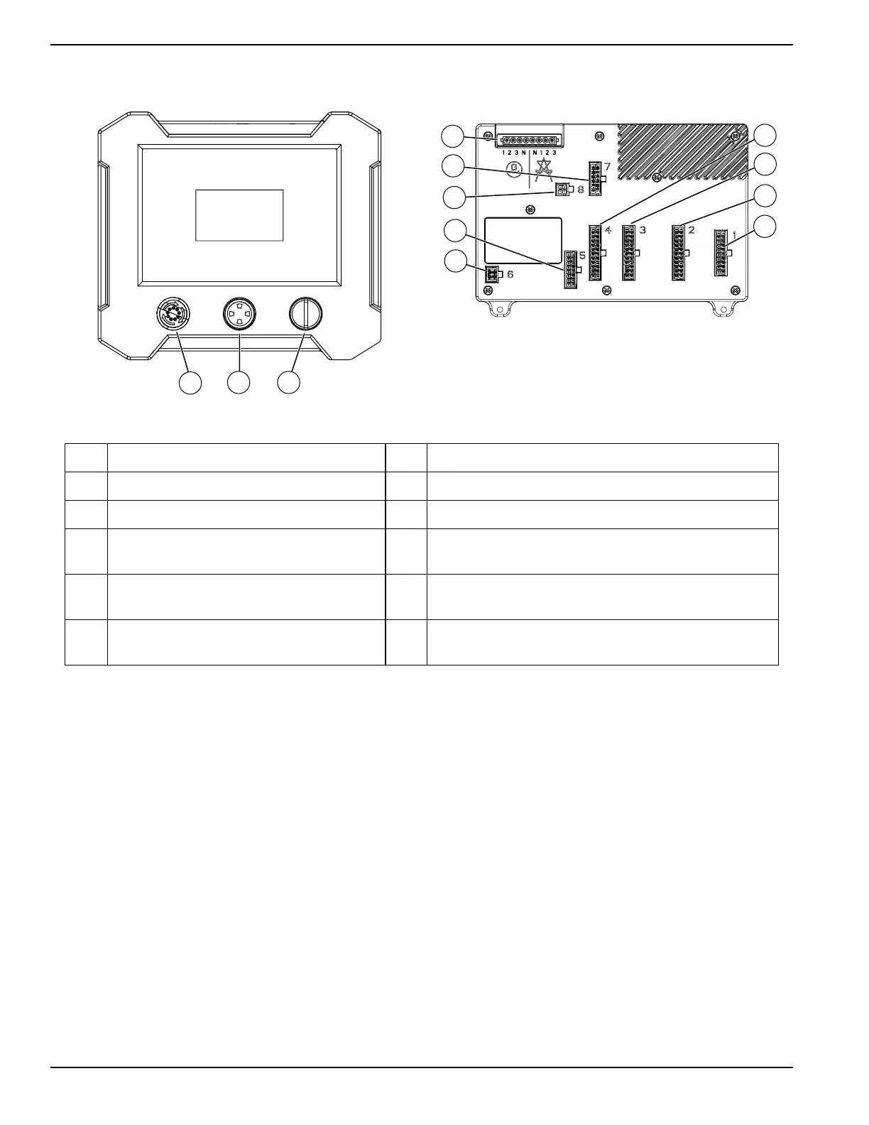
Connections
E
D
F
G
H
I
J
K
L
009394
B C
A
009393
Figure 2-1. Controller Connections
A Emergency Stop Button G (BS5) J5 digital inputs
B Alarm Horn H (BS6) J6 Connectivity Server power and RS-485
C AUTO/OFF/MANUAL Keyswitch I (BS4) J4 analog inputs, 5 V analog reference
D
(BS9) J9 utility sensing generator high
voltage sensing connections
J
(BS3) J3 CT inputs, analog inputs, analog outputs,
analog coolant level input
E
(BS7) J7 Generac CAN, watchdog digital
output, peripheral module power
K (BS2) J2 digital outputs
F (BS8) J8 J1939 CAN L
(BS1) battery connection, 12 V reference, RPM, RS-
485