Owner’s Manual for Power Zone Pro Main Controller 15
Installation and Operation
Pin Map
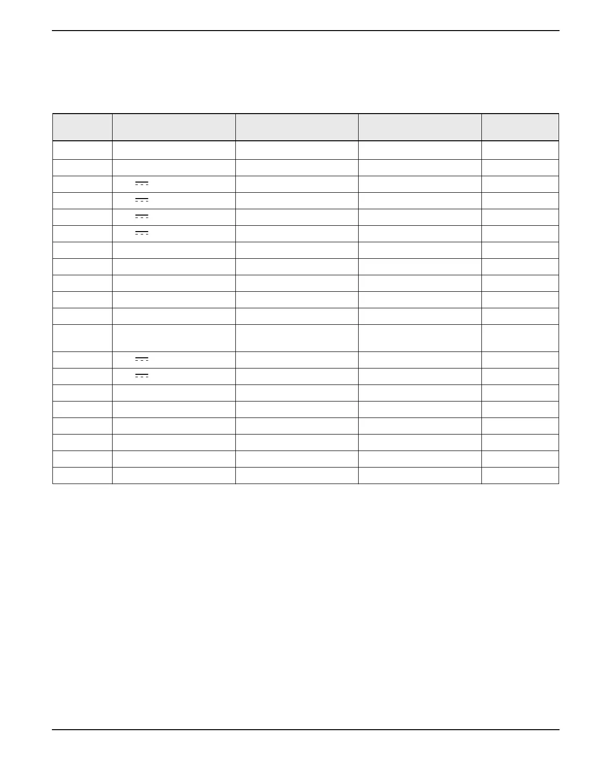
NOTE: See Table 3-1 through Table 3-9. “(BS1)” through “(BS9)” indicates connector reference designator used in
the harness drawing.
Table 3-1. J1 Connector
Pin Name Description
Configured Default
NA = Not Configurable
Wire # (Default)
(BS1) J1-1
RS-485 (+) #1 RS-485 #1 - RAP, etc.
Modbus
®
Master
390
(BS1) J1-2 RS-485 (-) #1 RS-485 #1 - RAP, etc. Modbus Master 391
(BS1) J1-3 12 V
Analog Sensor Supply NA
(BS1) J1-4 12 V
Analog Sensor Supply NA
(BS1) J1-5 12 V
Analog Sensor Supply NA
(BS1) J1-6 12 V
Analog Sensor Supply NA
(BS1) J1-7 N.C. No Connect NA
(BS1) J1-8 Battery (+) Positive Battery Connection NA
(BS1) J1-9 Battery (+) Positive Battery Connection NA
(BS1) J1-10 Battery (+) Positive Battery Connection NA 15A
(BS1) J1-11 RS-485 Ground Reference #1 RS-485 #1 Ground Modbus Master 0A
(BS1) J1-12
RS-485 Shield #1 RS-485 #1 Communications
Shield
Modbus Master SHLD
(BS1) J1-13 12 V
Analog Sensor Supply NA
(BS1) J1-14 12 V
Analog Sensor Supply NA
(BS1) J1-15 Mag Pickup (-) Primary Mag Pickup Sensor Engine Speed 0
(BS1) J1-16 Mag Pickup (+) Primary Mag Pickup Sensor Engine Speed 79
(BS1) J1-17 Mag Pickup Shield Primary Mag Pickup Sensor Engine Speed SHLD
(BS1) J1-18 Battery (-) Negative Battery Connection NA 0
(BS1) J1-19 Battery (-) Negative Battery Connection NA
0
(BS1) J1-20 Battery (-) Negative Battery Connection NA 0