Model 4802A
9
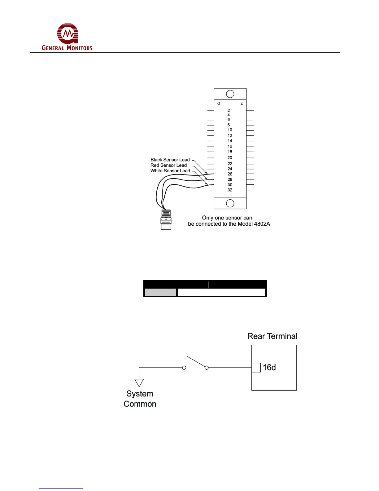
Figure 31 illustrates the Sensor/Controller connections.
Figure 31 – Sensor/Controller Connections
3.3.6 Card Test Switch
The terminal designation for the Card Test Input is:
Label Term Description
CT 16d Switch Connection
Figure 32 – Terminal Designation for Card Test Input
Figure 33 is a block diagram that shows the switch connections for the Card Test
feature.
Figure 33 - Switch Connections for Card Test Feature
The Card Test Input is provided so that the user can access the Card Test feature
remotely. One end of a normally open SPST switch is connected to this termination. The
other end is connected to system common. To activate the feature, simply press and
hold the switch for as long as the test time is to be run.