Model 4802A
10
3.3.7 Analog Output Signal
The terminal designations for the Analog Output Signal are:
Label Term Description
AO+ 20d Analog Signal (plus)
AO- 22d Analog Signal (minus)
Figure 34 – Terminal Designations for Analog Output
NOTE - If the Analog Signal is not used a jumper must be placed between 20d & 22d.
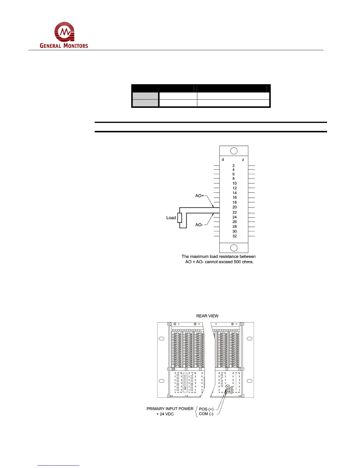
Figure 35 is a diagram of the Analog Signal connections.
Figure 35 – Analog Signal Connections
Figure 36 indicates where the power connections for the chassis are made.
Do not daisy chain +24V and Common on chassis. Apply separate power to each
chassis.
Figure 36 – Power Connections