Model 4802A
31
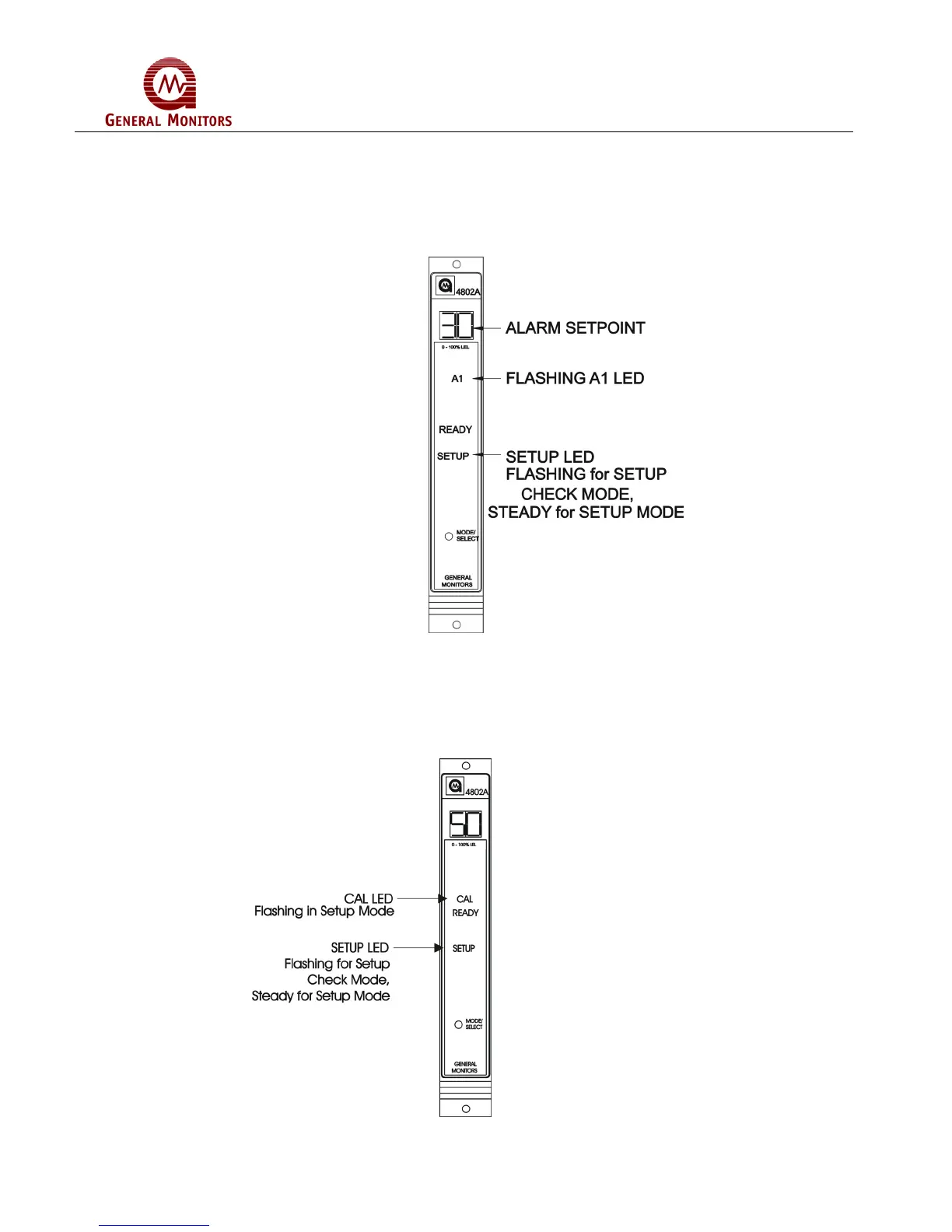
The last A1 alarm option to appear on the display will be the alarm set point (trip level).
If this level is reached or exceeded the A1 alarm outputs will activate. The display will
indicate the current A1 alarm set point (Figure 55). Press the Mode/Select switch
repeatedly, until the desired A1 alarm set point appears on the display (10 to the A2 set
point in increments of 5). The A1 set point cannot be set higher than the A2 set point. 30
is the factory default for this selection.
Figure 55 – A1 Set Point Option
5.4.5 Calibration Level Option
After the A1 alarm options have been selected, the user will choose the calibration level
(Figure 56). The CAL LED will flash and display will indicate current calibration level.
The acceptable range, in % LEL (lower explosive limit), is between 25 and 90, inclusive.
50% is the factory default for this selection.
Figure 56 – Calibration Level