Model 4802A
36
Password
i
n
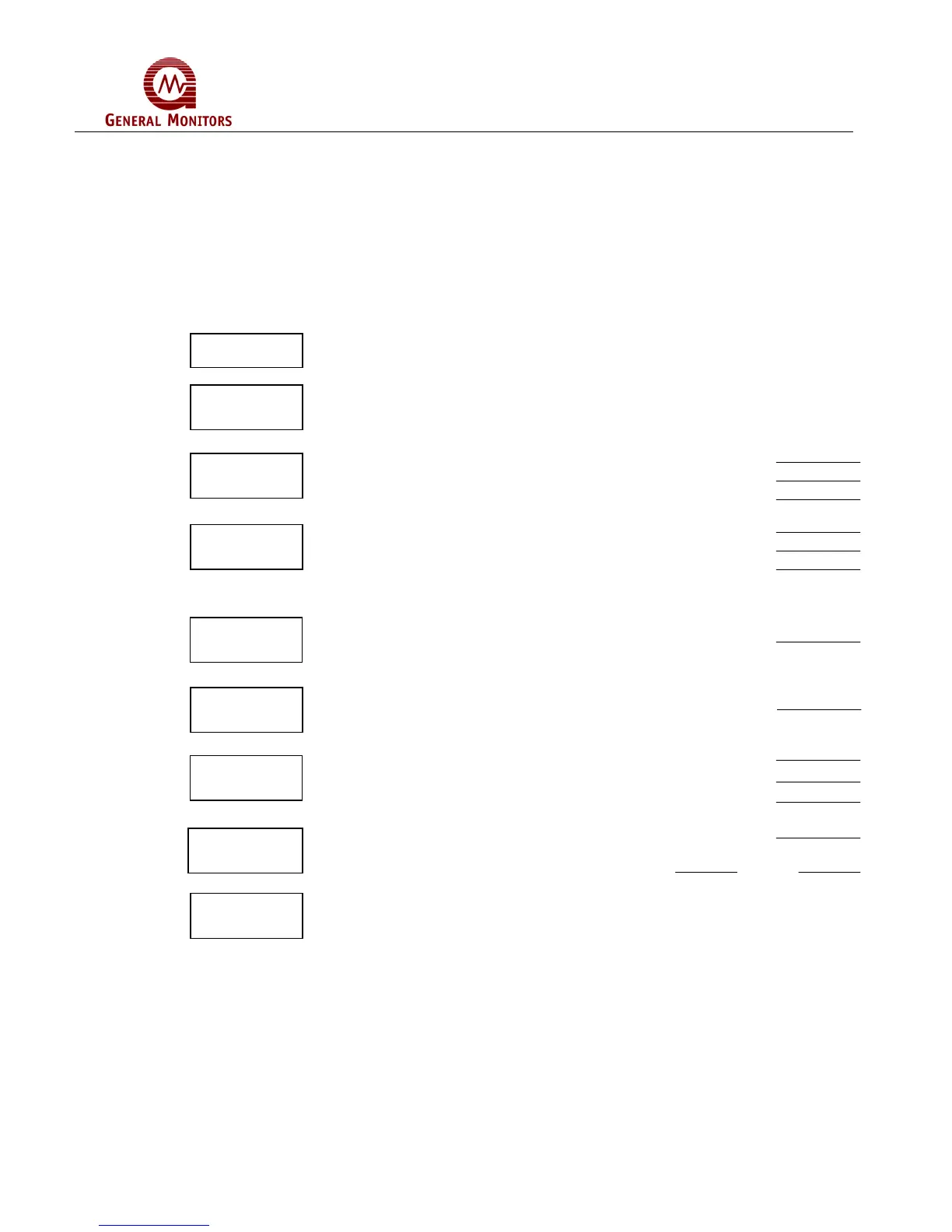
5.6 Setup Mode Selection Block Diagram
This section is provided to aid the operator in making selections during the Setup Mode.
It is recommended that the operator fill-in the selections in the proper blanks and then
use this page as a reference while programming the Model 4802A. The blocks shown
below indicate the order of options in the Setup Mode. To the right of each block is a
description of the choices that are available for that option. More information about
making each selection is provided in Section 5.4.
Enter the Password, if the Password is enabled.
Enter the Inhibit Mode, if desired.
ENTER SELECTION
Set the Energized (En) / De-Energized (dE) Option
Set the Latching (LA) / Non-Latching (nL) Option
Set the A2 alarm set point (from 10 to 60, in increments of 5)
Set the Energized (En) / De-Energized (dE) Option
Set the Latching (LA) / Non-Latching (nL) Option
Set the A1 alarm set point (from 10 to 60, in increments of 5)
The A1 Set Point cannot be higher than the A2 Set Point
Set the calibration level, LEL (from 25 to 90, in increments of 1)
Set the Fault Activate (Ac) or not (nA) during Inhibit Mode
Display will indicate “ct” for 5 seconds
Set the ramp time for the Card Test Mode (3 or 10 seconds)
Set the Alarm outputs for Active (Ac) or not Active (nA)
Set the Password to be Disabled (Pd) or Enabled (PE)
If the Password is Enabled:
Set the password digits Left Right
After all of the options have been selected, the 4802A will enter the Setup
Check Mode.
Password
Inhibit
M
?
A2 Alarm
i
n
A1 Alarm
i
n
Calibration
L
v
l
Fault/Inhibit
i
n
Card Test
i
n
Setup
h
k M