January 2012Section 4 • Repair Procedures
4 - 62 GS-30 • GS-32 • GS-46 • GS-47 Part No. 228901
SCISSOR COMPONENTS
16 Install the fasteners removed in 14 to the
number 1 inner arm pivot bracket and chassis.
Tip-over hazard. Failure to install
the fasteners securing the number
1 inner arm pivot bracket to the
chassis, could result in the
machine tipping over, causing
death or serious injury.
17 Connect the battery pack to the machine.
18 Turn the key switch to the ground control
position.
19 Press and hold the ground control scroll up and
scroll down buttons.
20 Pull out the red Emergency Stop button to the
on position at the ground controls.
21 Using the ground control menu buttons,
navigate to Service Override Mode. Select
Service Override Mode.
Note: The machine must be in Service Override
Mode to raise the platform. While in Service
Override Mode, only the GCON will operate with
limited functionality. The platform will raise a
predetermined amount of time and stop.
22 Raise the platform and return the safety arm to
the stowed position.
23 Fully lower the platform to the stowed position.
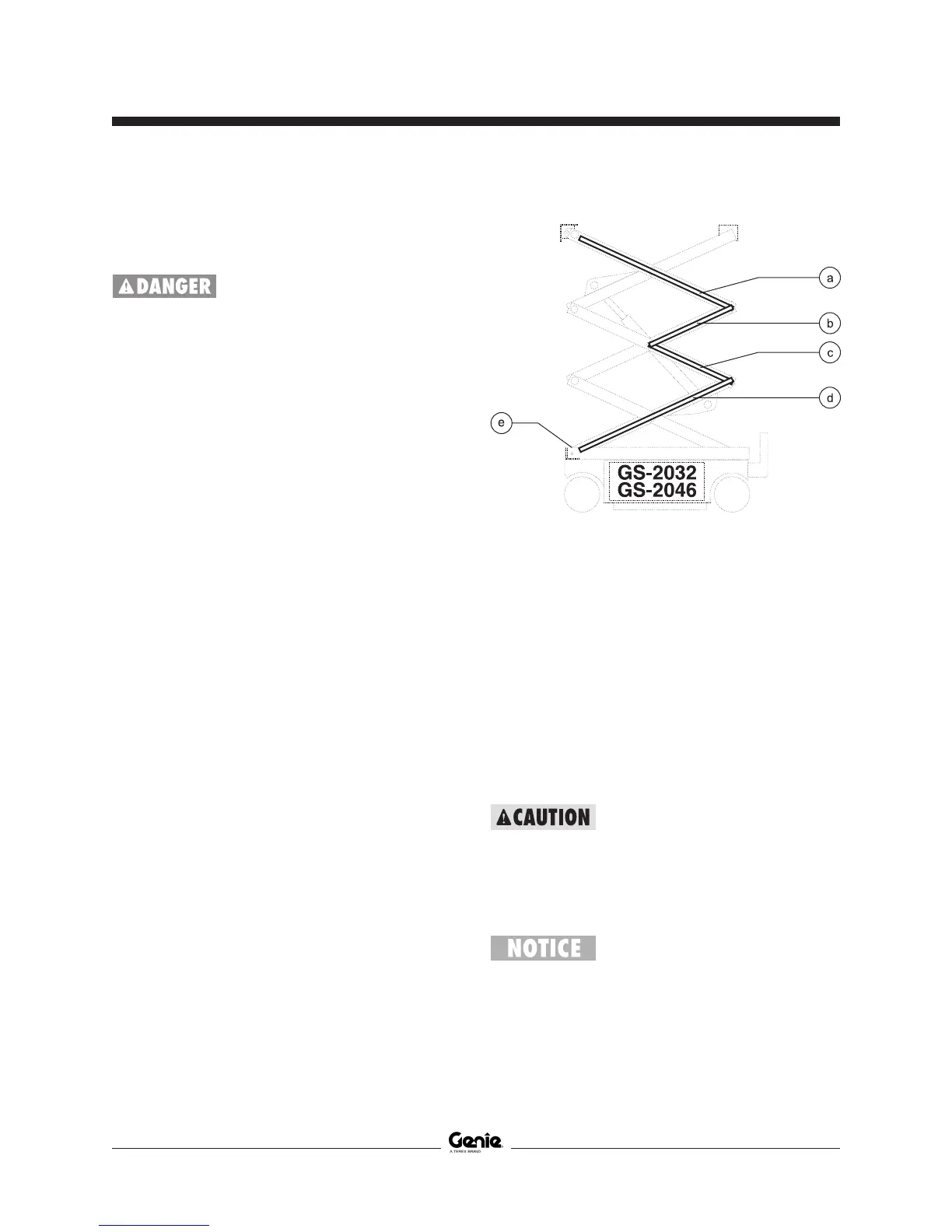
Cable bridge legend and platform height
sensor legend
a cable bridge 3
b cable bridge 2A
c cable bridge 2B
d cable bridge 1
e platform height sensor
24 Remove the platform. See 10-1,
How to
Remove the Platform.
25 Support and secure the entry ladder to an
appropriate lifting device.
26 Remove the fasteners from the entry ladder and
remove the entry ladder from the machine.
Crushing hazard. The entry ladder
may become unbalanced and fall
if not properly supported and
secured to the lifting device.
27 Remove the cables from the number 3 cable
bridge and lay them off to the side.
Component damage hazard.
Cables can be damaged if they
are kinked or pinched.
 Loading...