January 2012Section 4 • Repair Procedures
4 - 18 GS-30 • GS-32 • GS-46 • GS-47 Part No. 228901
Manifolds
Index Schematic
No. Description Item Function Torque
— Coil nut (item F) .................................................................................................................... 4-5 ft-lbs / 5-7 Nm
— Coil nut (items E and H) ....................................................................................................... 5-7 ft-lbs / 7-9 Nm
1 Diagnostic nipple ....................................... A ......................... Testing
2 Check disc ................................................. B ......................... Steer circuit ............................ 18 ft-lbs / 24 Nm
3 Relief valve,
1800 to 3700 psi / 124 to 255 bar ............. C ......................... Lift relief .................................. 20 ft-lbs / 27 Nm
4 Check valve, 10 psi / 0.7 bar ..................... D ......................... Drive circuit............................. 20 ft-lbs / 27 Nm
5 Solenoid valve, 3 position 4 way ............... E ......................... Drive forward/reverse ............. 25 ft-lbs / 34 Nm
6 Solenoid valve, 3 position 4 way ............... F ......................... Steer left/right ......................... 25 ft-lbs / 34 Nm
7 Flow regulator and relief valve,
0.75 gpm / 2.8 L/min,
1500 psi / 103 bar ...................................... G ......................... Steer circuit ............................ 26 ft-lbs / 35 Nm
8 Solenoid valve, 2 position 4 way ............... H ......................... Platform up ............................. 25 ft-lbs / 34 Nm
9 Relief valve,
3700 psi / 255 bar maximum ..................... I .......................... System relief........................... 20 ft-lbs / 27 Nm
5-1
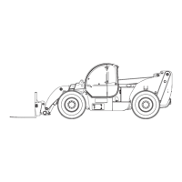
Function Manifold Components -
GS-1530, GS-1532, GS-1930 and GS-1932
The function manifold is mounted under the machine, between the module trays.
How to Install a Valve Cartridge
1 Dip the cartridge in clean oil to lube the O-rings.
2 Screw the cartridge in by hand until the top
O-ring is met, then torque to specification.
3 If required, install the valve coil(s) onto the
valve stem. Install the coil nut onto the valve
stem and torque to specification.
 Loading...