Section 4 • Repair ProceduresJanuary 2012
Part No. 228901 GS-30 • GS-32 • GS-46 • GS-47 4 - 27
1
3
CA and CB
CF
4
Retract
Extend
CE
2
CG
FRONT
OUTRIGGERS
Y35
Y36
1
3
CC and CD
CF
Extend
Retract
CE
2
CG
REAR
OUTRIGGERS
4
Y33
Y34
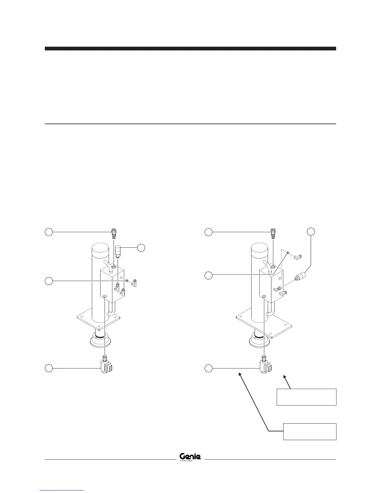
Note: 'alpha-numeric' callouts
refer to corresponding notes
on the electrical schematic
Note: 'alpha' callouts refer
to corresponding notes on
the hydraulic schematic
MANIFOLDS
5-7
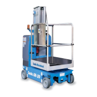
Outrigger Cylinder Manifold Components -
GS-3232
The front outrigger cylinders are located behind the inspection doors at the battery side and at the ground
control side of the machine. The rear outrigger cylinders are located inside the outrigger enclosures at the
rear of the machine.
How to Install a Valve Cartridge
1 Dip the cartridge in clean oil to lube the O-rings.
2 Screw the cartridge in by hand until the top
O-ring is met, then torque to specification.
3 If required, install the valve coil(s) onto the
valve stem. Install the coil nut onto the valve
stem and torque to specification.
Index Schematic
No. Description Item Function Torque
— Coil nut (item CA, CB, CC, CD) ............................................................................................ 4-5 ft-lbs / 5-7 Nm
1 Solenoid valve, 2 position 2 way ............... CA, CB, CC, CD . Outrigger extend/retract ......... 25 ft-lbs / 34 Nm
2 Orifice - plug,
0.037 inch / 0.94 mm ................................. CE ...................... Outrigger retract
3 Check valve, pilot operated ....................... CF ...................... Retract flow control ............ 20 ft-lbs / 27.1 Nm
4 Pressure Transducer ................................. CG ...................... Outrigger auto level ............. 16 ft-lbs / 21.7 Nm
 Loading...