Section 4 • Repair ProceduresJanuary 2012
Part No. 228901 GS-30 • GS-32 • GS-46 • GS-47 4 - 81
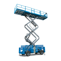
SCISSOR COMPONENTS
26 Remove the fasteners from the entry ladder and
remove the entry ladder from the machine.
Crushing hazard. The entry ladder
may become unbalanced and fall
if not properly supported and
secured to the lifting device.
27 Remove the cables from the number 5 cable
bridge and lay them off to the side.
Component damage hazard.
Cables can be damaged if they
are kinked or pinched.
28 Disconnect the number 5 cable bridge from the
number 5 outer arm (index #17) and remove
the cable bridge from the machine.
29 Remove the retaining fasteners from the
number 6 pivot pin (index #1).
30 Use a soft metal drift to remove the number 6
pivot pin (index #1). Remove the platform
mount bracket from the machine.
31 Attach a lifting strap from an overhead crane to
the number 5 outer arm at the ground control
side (index #17).
32 Remove the retaining fasteners from the
number 5 center pivot pin (index #2) at the
ground control side.
33 Place a rod through the number 5 center pivot
pin at the ground control side (index #2) and
twist to remove the pin.
34 Remove the retaining fasteners from the
number 5 pivot pin (index #18) at the non-steer
end.
35 Use a soft metal drift to remove the number 5
pivot pin (index #18) from the non-steer end of
the machine. Remove the number 5 outer arm
at the ground control side (index #17) from the
machine.
Crushing hazard. The number 5
outer arm at the ground control
side (index #17) may become
unbalanced and fall if not properly
supported when removed from the
machine.
36 Attach a lifting strap from an overhead crane to
the number 5 outer arm at the battery side
(index #17).
37 Remove the retaining fasteners from the
number 5 center pivot pin (index #2) at the
battery side.
38 Place a rod through the number 5 center pivot
pin at the battery side (index #2) and twist to
remove the pin.
39 Remove the number 5 outer arm (index #17)
from the machine.
Crushing hazard. The number 5
outer arm (index #17) may
become unbalanced and fall if not
properly supported when removed
from the machine.
40 Attach a lifting strap from an overhead crane to
the number 5 inner arm (index #16). Raise the
arm to a vertical position.
 Loading...