January 2012Section 4 • Repair Procedures
4 - 30 GS-30 • GS-32 • GS-46 • GS-47 Part No. 228901
12 Turn the key switch to ground control and pull
out the red Emergency Stop button to the on
position at both the ground and platform
controls.
13 Hold the lift relief valve with a wrench and
remove the cap (schematic item C).
14 While activating the platform up function, adjust
the internal hex socket clockwise, just until the
platform fully raises.
15 Fully lower the platform.
16 Add an additional 50 pounds / 22.7 kg to the
platform. Secure the additional weight.
17 Attempt to raise the platform.
Result: The power unit should not be able to lift
the platform.
Result: If the power unit lifts the platform, adjust
the internal hex socket counterclockwise until
the platform will not raise.
18 Install the relief valve cap.
19 Remove the weight from the platform.
20 Bleed the hydraulic system by raising the
platform to full height. If the pump cavitates or
the platform fails to reach full height, add
hydraulic oil until the pump is functioning
correctly. Do not overfill the hydraulic tank.
Component damage hazard. Do
not continue to operate the
machine if the hydraulic pump is
cavitating.
How to Adjust the
Lift Pressure Selector Valve
(GS-4047 only)
Note: The System Relief Valve and Platform Lift
Relief Valve must be adjusted before making and
an adjustment to the Lift Pressure Selector Valve.
Refer to
How to Adjust the System Relief Valv
e
and
How to Adjust the Platform Lift Relief Valve
in
this section.
Perform this test from the ground with the platform
controls. Do not stand in the platform.
Be sure that the hydraulic oil level is at the FULL
mark on the hydraulic tank.
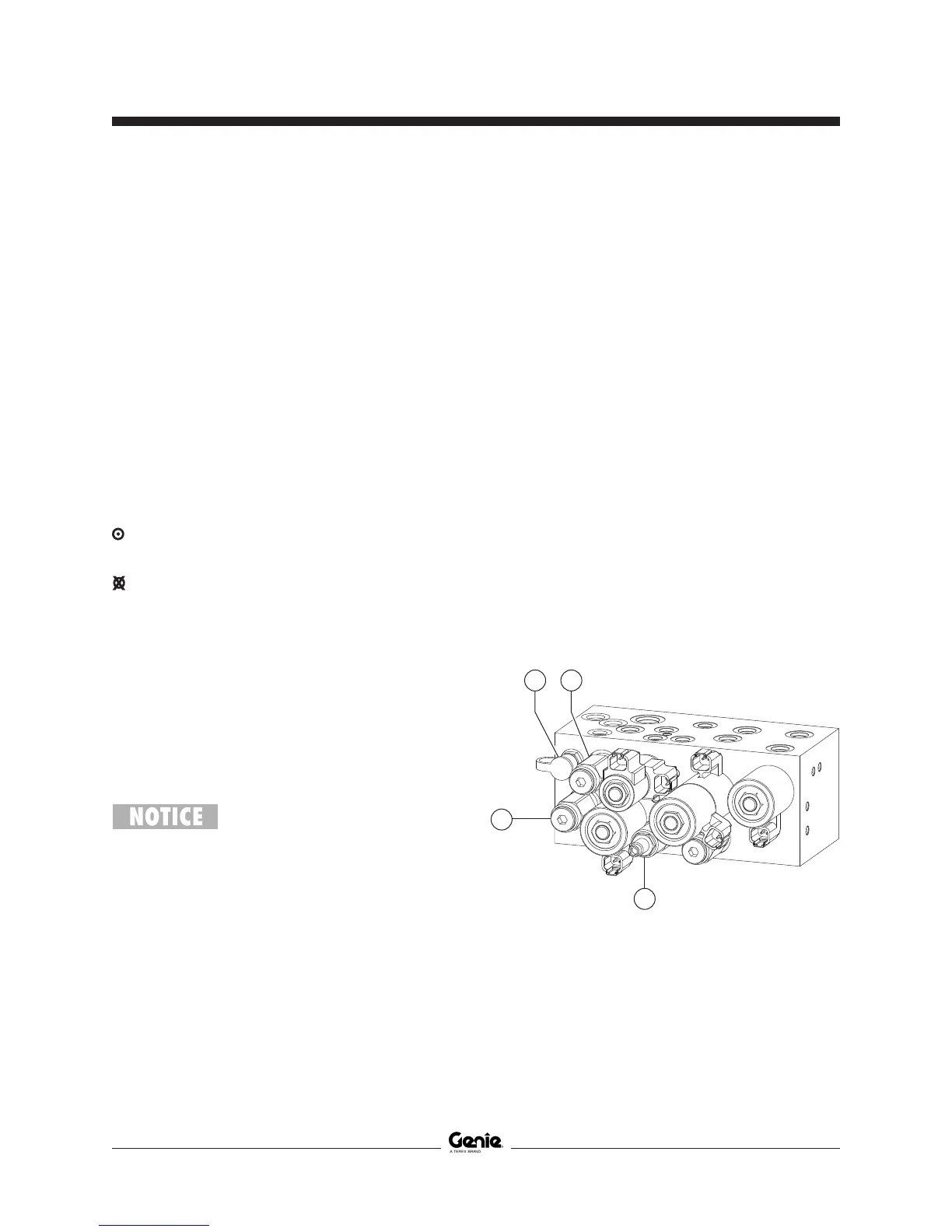
1 Locate the pressure selector relief valve on
the pressure selector manifold (schematic item
DM).
2 Connect a 0 to 5000 psi / 0 to 350 bar
pressure gauge to the test port on the function
manifold (schematic item DA).
GS-4047
a test port
b system relief valve
c steer relief valve
d lift relief valve
c
a b
d
MANIFOLDS
 Loading...