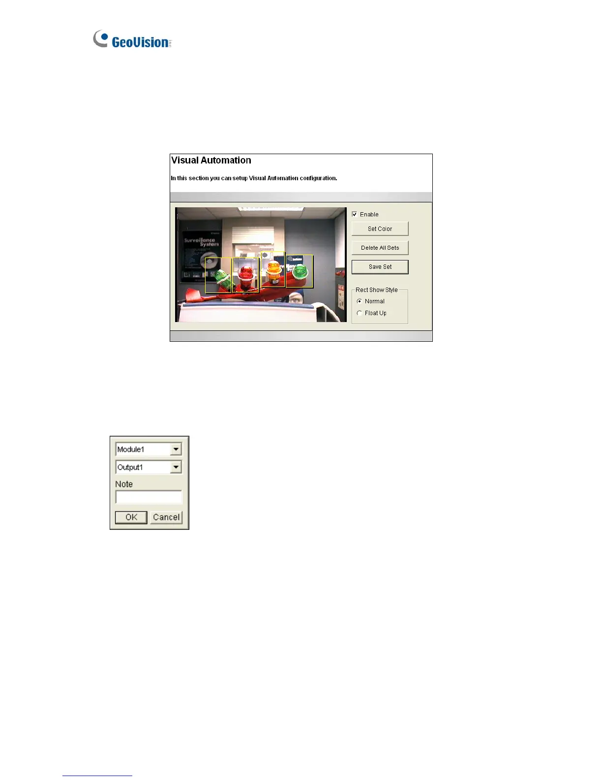
4.1.6 Visual Automation
Note this function is only supported by cameras with I/O function. This intuitive feature helps
you automate any electronic device by triggering the connected output device. When you click
on the image of the electronic device, you can simply change its current state, e.g. light ON.
Figure 4-10
1. Select the Enable option.
2. Drag an area on the image of the electronic device. This dialog box appears.
Figure 4-11
3. Assign the connected module and output device. In the Note field, type a note to help you
manage the device. Click OK to save the settings.
4. To change the frame color of the set area, click the Set Color button.
5. To emboss the set area, select Float Up; or keep it flat by selecting Normal.
6. Click the Save Set button to apply the settings.
7. To perform the function, see 3.13 Visual Automation.
98
 Loading...