Page 11
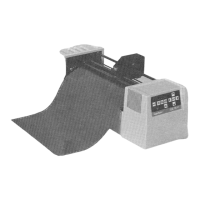
Vacuum valves (DCS 2500 only - locations vary)
Vacuum starter box (typical location)
Hardware Description
(1) Emergency Stop (E-Stop) Switches and (2) E-
Stop Bumper Arms
Two red E-Stop switches (see Figure 2) and four yellow E-Stop bumper
arms (see Figure 3) are located on the cutter. An additional E- Stop
switch is located on the control box.
The E-Stop function should be used when there is danger to people, the
cutter, or the cut material.
This function is activated when:
¨ Any of the two red E-Stop switches are pushed.
¨ Any of the four yellow E-Stop bumper arms come into contact with a
person or object.
This function immediately shuts the system down. It stops all motors,
deactivates all tools, and removes all servo power supplies. It also stops
all motion.
Only the computer is energized after an E-Stop. Data is saved and an E-
Stop recovery procedure must be completed before using the cutter again.
See E-Stop recovery procedure.