Do you have a question about the Gigabyte MNJ190I-FH and is the answer not in the manual?
| Form Factor | Mini-ITX |
|---|---|
| LAN | Realtek GbE LAN |
| CPU | Intel Celeron J1900 (Quad-Core, 2.0GHz, up to 2.42GHz) |
| Memory Slots | 2 x SO-DIMM |
| Max Memory Support | 8GB |
| PCIe Slots | 1 x PCIe x1 |
| Storage Interface | 2 x SATA 3Gb/s |
| Audio | Realtek ALC887 |
| Video Outputs | HDMI |
| USB Ports | 4 x USB 2.0 ports (2 on the back panel, 2 available through the internal header) |
Essential guidelines to prevent damage during installation.
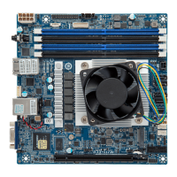
Detailed technical specifications of the motherboard and its components.
Step-by-step guide for installing memory modules correctly.
Description and function of all ports located on the motherboard's back panel.
Identification and descriptions of internal connectors on the motherboard.
Details on the 4-pin 12V power connector for motherboard components.
Information about the DC input power connector for the motherboard.
Pinout and description for the SATA 7+15 pin header.
Specifications for the SATA 3Gb/s connector supporting single SATA devices.
Details of the SATA HDD power connector and its pin definitions.
Information on serial port connectors and their pin assignments for communication.
Configuration options for COM2 serial port using jumpers for RS232/422/485 modes.
Technical explanation of LVDS signaling and pinout for the LVDS connector.
Jumper settings to enable or disable the LVDS function on the motherboard.
Jumper configuration for selecting the LVDS voltage supply (3.3V or 5V).
Jumper for controlling LCD power, allowing selection between external control or motherboard control.
Connector for controlling LVDS backlight, including enable/disable signals.
Connector for the LVDS backlight enable signal, linking to the BKL_CN pin.
Details on USB 2.0/1.1 headers for connecting internal USB ports via brackets.
General Purpose Input/Output connector pinout for custom hardware integration.
Header for connecting the chassis front panel audio module (HD/AC'97).
Connector for audio amplifier output, specifying left and right channel pins.
Header for connecting chassis front panel components like power switch and LEDs.
Pinout for the parallel printer port connector (LPT).
Header to detect unauthorized opening of the computer chassis.
Information on the HDMI port, including HDCP compliance and supported resolutions.
Header for connecting the CPU fan, supporting speed control and proper orientation.
SMBus connector pinout for system management interface.
Socket for the CMOS battery, essential for maintaining BIOS settings when power is off.
Jumper to reset CMOS values to factory defaults, useful for troubleshooting.
Overview of BIOS functions, access method, and general warnings.
Descriptions of the main BIOS setup menus: Main, Advanced, Chipset, Security, Boot, Save & Exit.
Introduction to the BIOS Main Menu screen and navigation keys.
Explanations for items like Project Name, BIOS Version, Build Date, and MAC Address.
Overview of the Advanced menu, which contains hardware component configuration options.
Configuration related to Advanced Configuration and Power Interface (ACPI) settings.
Settings for the Super IO chip, including serial and parallel port configurations.
Configuration options for Serial Port 2 and Serial Port 3.
Configuration options for Serial Port 4 and Serial Port 5.
Configuration options for Serial Port 6.
Settings for the parallel port, including device settings and mode.
Detailed explanations of Super IO chip settings, serial, and parallel port modes.
Real-time display of system temperature, voltage, and fan speed status.
Configuration for waking the system from S5 state at a specific date and time.
Settings related to CPU features like Virtualization, EIST, and Turbo Mode.
Displays detailed technical specifications of the installed CPU.
Configuration for SATA controller mode (IDE/AHCI) and serial ATA port status.
Settings for Compatibility Support Module (CSM) to manage legacy and UEFI boot options.
Further details on CSM configuration, including OpROM execution order for PCI devices and video.
Configuration for USB controller modes, specifically XHCI (USB 3.0) hand-off.
Settings related to onboard devices like LAN, Audio, AC Power Loss, and Boot Display.
Additional Chipset settings including backlight brightness, cash drawer power, and watchdog timer.
Options for setting Administrator and User passwords to protect system access.
Configuration for Secure Boot functionality, including system mode and boot options.
Management of Secure Boot keys, including provisioning and enrollment of factory defaults.
Detailed operations for managing Authorized Signature Databases (DB) and Forbidden Signature Databases (DBX).
Settings for configuring boot device priorities and screen logo display.
Options for saving changes, discarding changes, restoring defaults, and booting from EFI Shell.