4.0
ENG
GLT
Ω
L
IFT
O
PERATION
M
ANUAL
Page | 61
Code IMQ20
Rev. 0
of
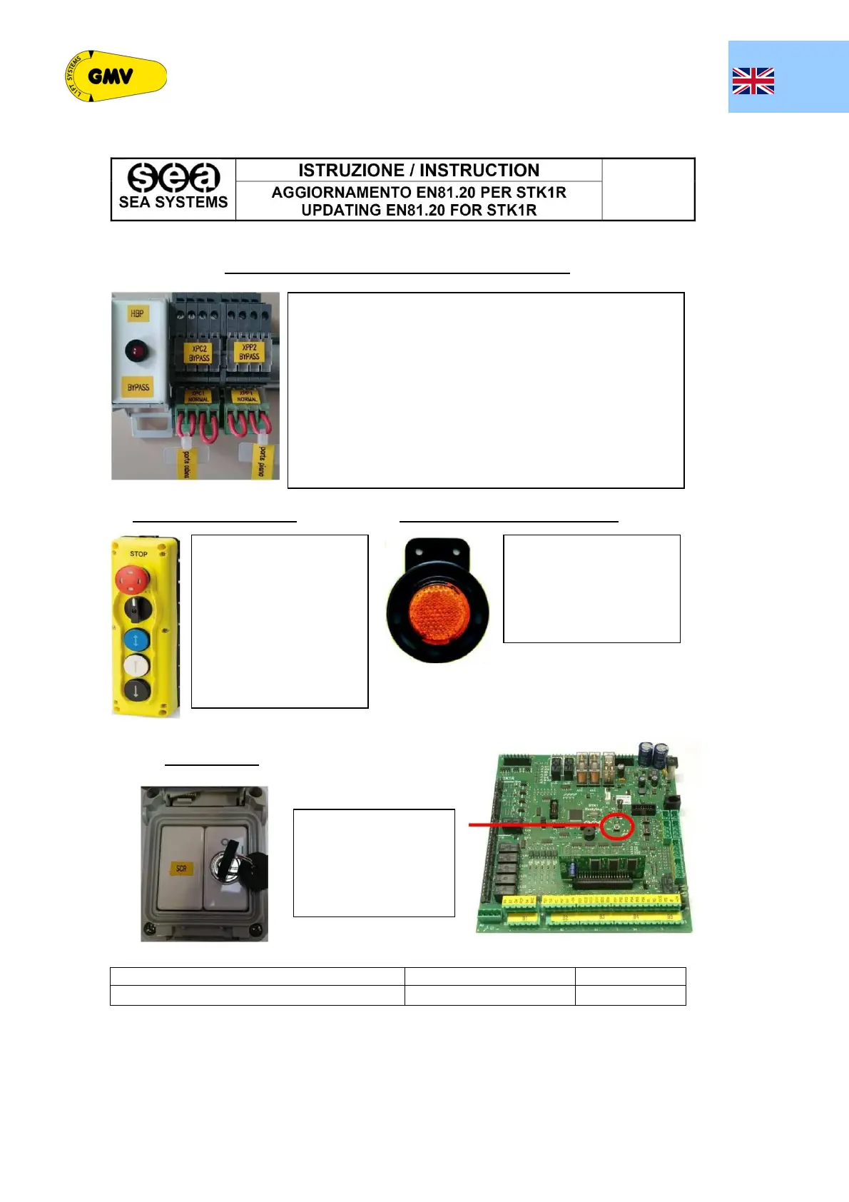
CONNECTORS FOR CAR OR LANDING DOORS BYPASS
The cabinet features connectors used to individually bypass the landing
doors or the car doors.
The connector for bypassing the car doors is identified with XPC, while the
connector for bypassing the landing doors with XPP.
Under normal operating conditions, the XPC connector is inserted in XPC1
and the XPP connector in XPP1.
To bypass the car doors it is necessary to move the XPC connector and
insert it into XPC2, while to bypass the landing doors it is necessary to
move the XPP connector into XPP2. The HBP LED lights up in the bypass
condition.
The XPC and XPP must NOT be moved simultaneously as the maintenance
push-button panel would not work.
Once the bypass has been inserted, it is possible to move the car using the
maintenance push-button panels.
PIT PUSH-BUTTON PANEL TRAVEL INDICATOR WITH BYPASS
A Pit inspection push-button
panel must be provided to move
the car even with the bypass
connector inserted.
The rotation of the switch from
Normal to Inspection requires,
once the operation is completed,
a Reset from a device outside
the shaft, protected by a key
A luminous and audible indicator
under the car comes on only
when the car moves with the
maintenance push-button
panels and a bypass connector
inserted.
RESET DEVICE
This reset device must be
installed outside the shaft
either by an SCR key or by
the control panel provided
they are located near the pit
access doors
ISSUED BY (Role):
Issue DATE
PAGE
Electrical Design
26/03/2018
1 of 1