14
User Manual V1.5-2021-01-21 02 Installation Instructions
Reset
SMART METER
USB
L1
L2
L3
N
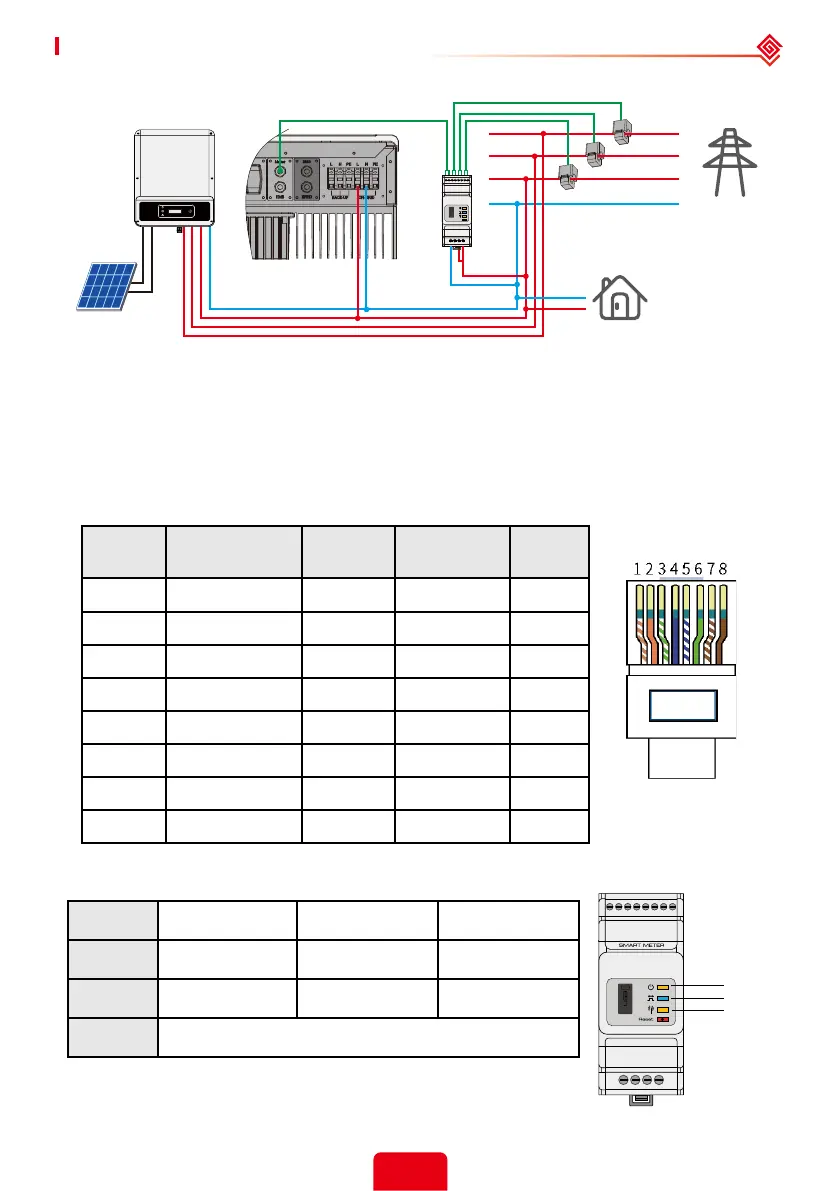
Detailed pin functions of each port on the SBP
BMS: CAN communication is congured by default. If 485 communication is used, please contact
the after-sales service to replace this with the correct communication cable.
GM3000
SBP
PV
3-Phase
Grid-Tied Inverter
House → Grid
Load
CT1
CT2
CT3
Grid
Note:
1. Please use the Smart Meter with 3 CTs in GoodWe product box.
2. CT cable is 3m as default, could be extended to a max of 5m.
3. Smart Meter communication cable (RJ45) is attached on the inverter ("To Smart Meter" cable), could
be extended to a max of 100m, standard RJ45 cable and plug must be used, as below:
Position Color BMS
Function
Smart
Meter
EMS
1 Orange & white 485_A2 NC 485_A
2 Orange NC NC 485_B
3 Green & white 485_B2 485_B1 485_A
4 Blue CAN_H NC NC
5 Blue & white CAN_L NC NC
6 Green NC 485_A1 485_B
7 Brown & white NC 485_B1 NC
8 Brown NC 485_A1 NC
Smart Meter LED indications
STATUS OFF ON Blinking
POWER Not working Working /
ENERGY / Importing Exporting
COM Single blink when data are transferred to the inverter
POWER
ENERGY
COM
 Loading...