16
User Manual V1.5-2021-01-21 02 Installation Instructions
123456
123456
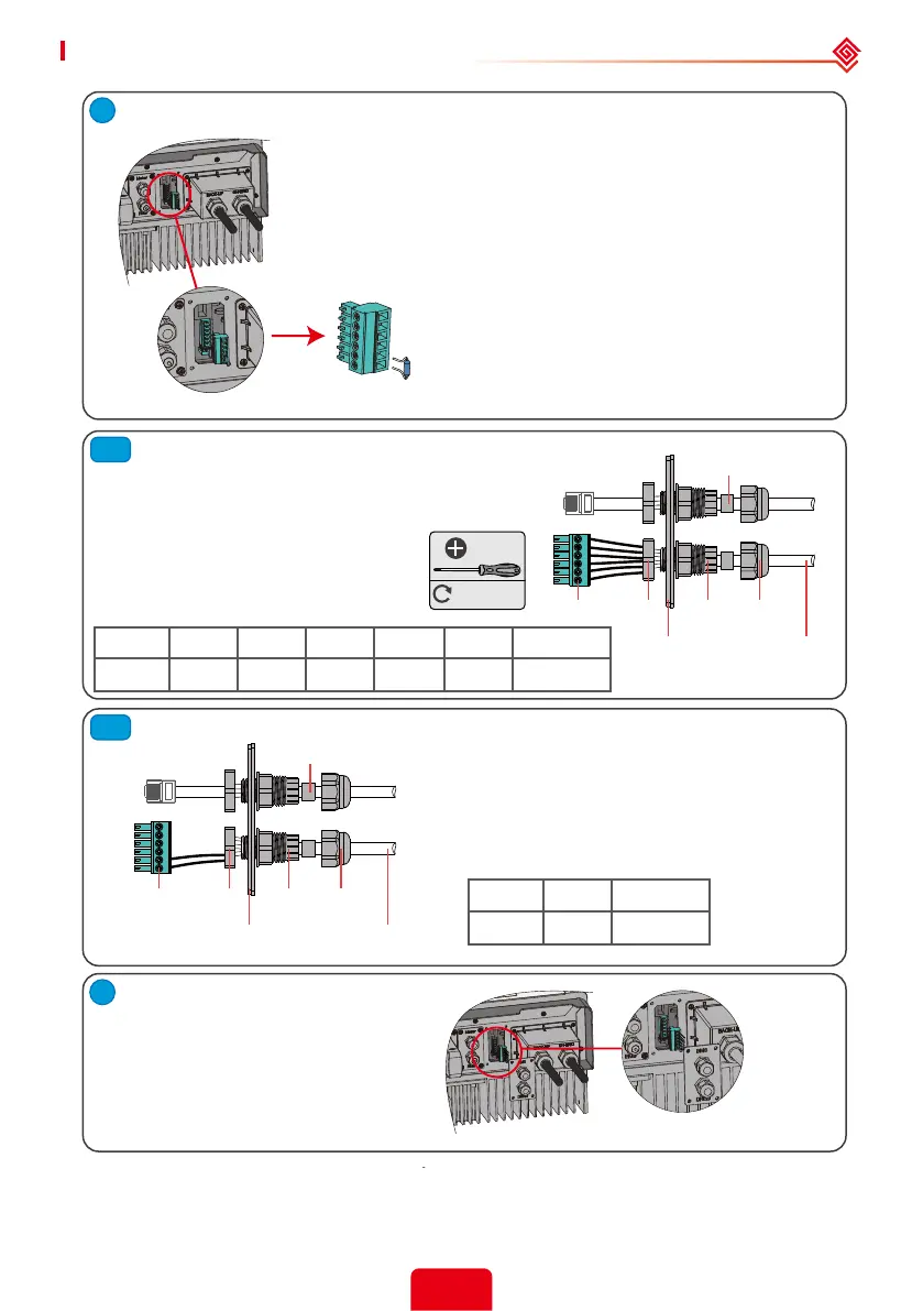
1. Plug out the 6-pin terminal and dismantle the resistor on it.
2. Plug the resistor out, leave the 6-pin terminal for next step.
Note: The 6-pin terminal in the inverter serves the same function as
DRED / Remote shutdown device. Please leave it in the inverter if no
external device are connected.
1. Put the cable through the plate.
2. Connect the cable on the 6-pin
terminal.
The function of each connection
position as below:
1. Put the cable through the plate.
2. Connect cable on the 6-pin terminal.
(Wiring from the No. 5 and 6 holes
respectively.)
The function of each connection position
as below:
Plug the terminal to the right
position of the inverter.
Single hole
seal ring
Single hole
seal ring
RS485
communication board
RS485
communication board
Screw
Screw
Cable
Cable
Screw Cap
Screw Cap
Insulator
Insulator
Nut
Nut
NO 1 2 3 4 5 6
Function DRM1/5 DRM2/6 DRM3/7 DRM4/8 REFGEN COM /DRMO
NO 5 6
Function REFGEN COM /DRMO
2.5.2 Earth Fault Alarm Connection
S-BP series inverter complies with IEC 62109-2 13.9. Fault indicator LED on the inverter cover will
light up and the system will email the fault information to customer.
For DRED
For Remote Shutdown
M2
0.2N·m
 Loading...