11
02 Installation Instructions User Manual V1.5-2021-01-21
Note:
1. Under on-grid mode, battery is protected from over discharge by DOD and discharge voltage, under
o-grid mode, it is protected by only discharge voltage in priority.
2. The DOD setting of a battery prevents the inverter from discharging battery reserve power. As soon
as the DOD is reached the load of building will only be supported by either PV power or from the grid.
If there are continuous days when little or no battery charging occurs, the battery may continue to
self-consume energy to support communications with the inverter. This behaviour is dierent between
battery manufactures products, however, if the SOC of the battery reaches a certain level the inverter will
boost the SOC back up. This protection mechanism safegurads the battery to falling to 0% SOC.
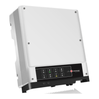
2.4.3 On-Grid & Back-Up Connection
An external AC breaker is needed for On-Grid connection to be isolated from grid when necessary.
Below are the requirements of On-Grid AC breaker.
1. Use a separate AC break for individual
inverter.
2. On AC side, the individual break should
be connected before loads (between
inverter and loads).
Wi-Fi
Reset/Reload
SYSTEM
GRID
BACK-UP
ENERGY
COM
Wi-Fi
BATTERY
FAULT
2019
Wi-Fi
Reset/Reload
SYSTEM
GRID
BACK-UP
ENERGY
COM
Wi-Fi
BATTERY
FAULT
2019
Wi-Fi
Reset/Reload
SYSTEM
GRID
BACK-UP
ENERGY
COM
Wi-Fi
BATTERY
FAULT
2019
AC Breaker
AC Breaker
AC Breaker
AC Breaker
Load
Grid
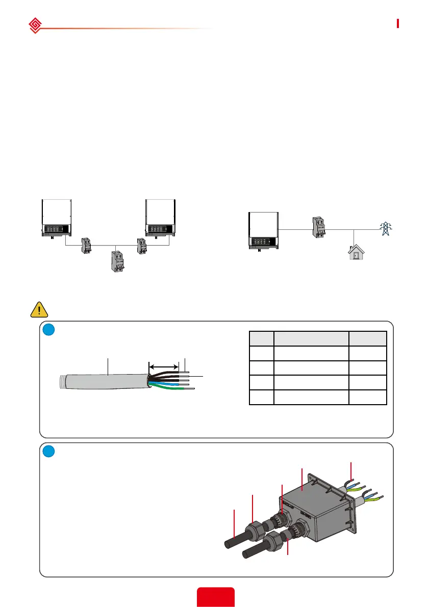
• On-grid wiring connection process is as below:
Make sure inverter inverter is totally isolated from any DC or AC power before connecting
AC cable.[5]
Prepare the terminals and AC cables according
to the right table.
Note:
1. Neutral cable shall be blue, line cable is black or brown (preferred) and protective earth cable yellow-green.
2. For AC cables, PE cable shall be longer than N&L cables, so that if in any case the AC cable slips or is taken
out, the protecting earth conductor will be the last to take the strain.
Cable Description Value
A Outside Diameter 11-12 mm
B Isolation section NA
C Conductor wire length 7-9 mm
D Conductor core section 6 mm
2
Put AC cable through the terminal
cover in the following sequence.
Note: Please use the terminals in
the accessories box.
Connection
Terminal
AC Cover
Insulator
Screw Cap
Cable
Single hole seal ring
A
B
C
D
1
 Loading...