16 GMC-I Messtechnik GmbH
1) Measuring Contact Current Without Tripping the RCD
Measuring Method
The instrument uses a measuring current of only 1/3 nominal
residual current for the determination of contact voltage U
IN
which occurs at nominal residual current. This prevents tripping of
the RCCB.
This measuring method is especially advantageous, because
contact voltage can be measured quickly and easily at any
electrical outlet without tripping the RCCB.
The usual, complex measuring method involving testing for the
proper functioning of the RCD at a given point, and subsequent
substantiation that all other systems components requiring pro-
tection are reliably connected at low resistance values to the
selected measuring point via the PE conductor, is rendered
unnecessary.
N-PE Reversal Test
An additional test is executed which deter-
mines whether or not N and PE have been
reversed. If reversal is detected, the popup
window shown at the right appears.
In order to prevent the loss of data in data processing
systems, perform a data backup before starting the
measurement, and switch off all power consumers.
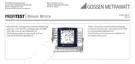
Start Measurement
Amongst other values,
contact voltage U
IN
and calculated earthing resistance R
E
appear at the display panel.
The measured earthing resistance value R
E
is acquired
with very little current. More accurate results can be
obtained with the selector switch in the R
E
position.
In the case of systems with RCCBs, the DC +
function can be selected.
Unintentional Tripping of the RCD due to Biasing Current within
the System
These can be measured by executing a voltage measurement
with the measuring adapter (2-pole). If bias currents should occur,
they can be measured with the help of a current transformer
clamp as described in section 15.1 on page 40. The RCCB may
be tripped during testing of contact voltage if extremely large
biasing currents are present within the system, or if a test current
was selected which is too great for the RCCB.
After contact voltage has been measured, testing can be
performed to determine whether or not the RCCB is tripped
within 400 ms, or 1000 ms, at nominal residual current.
Unintentional Tripping of the RCD due to Leakage Current in the
Measuring Circuit
Measurement of contact voltage with 30% nominal residual
current does not normally trip an RCCB. However, the trip limit
may be exceeded as a result of leakage current in the measuring
circuit, for example due to interconnected power consumers with
EMC circuits such as frequency converters and PCs.
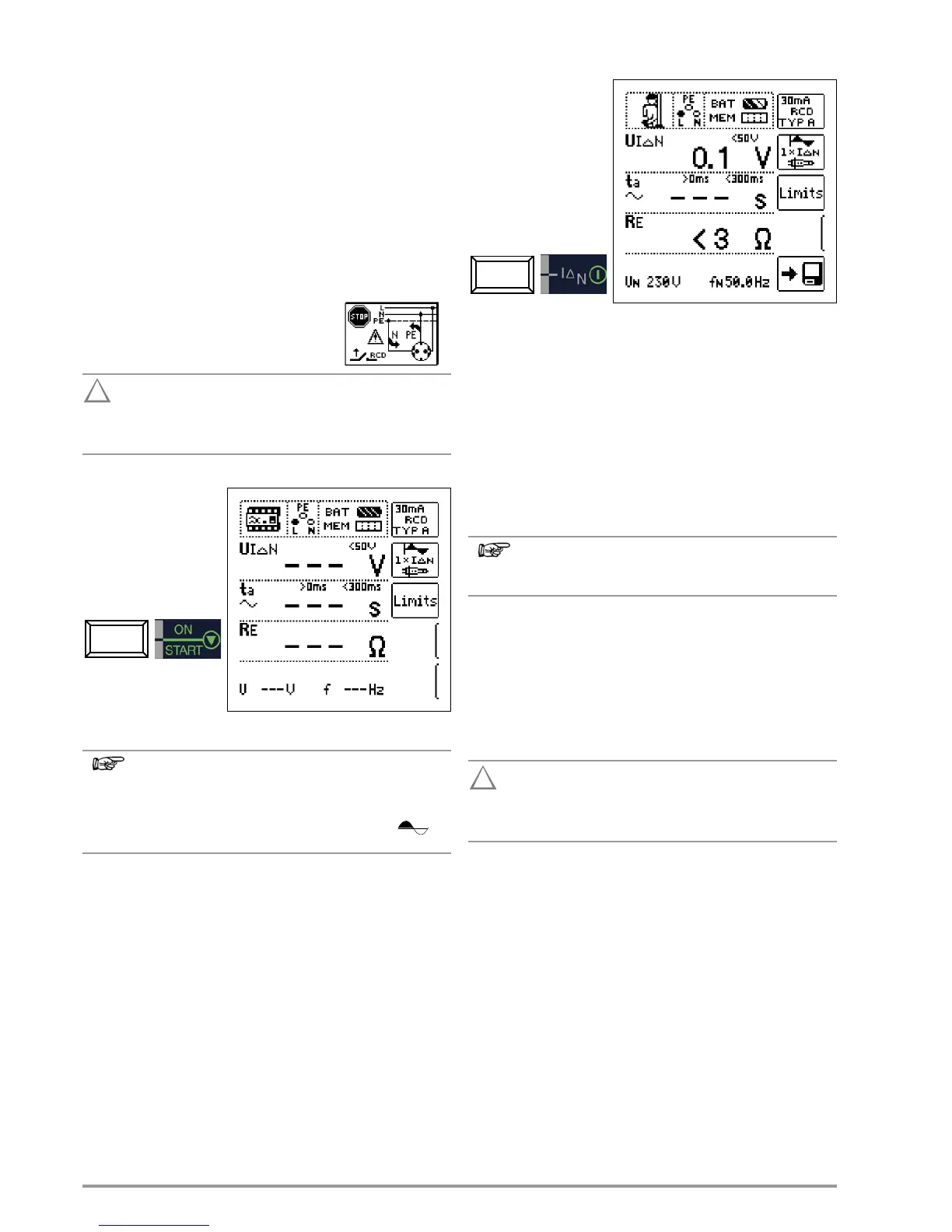
2) Tripping Test after the Measurement of Contact Voltage
Ð Press the I
N
key before on-time has expired (30 seconds).
The tripping test need
only be performed at
one measuring point for
each RCCB.
If the RCCB is tripped at nominal residual current, the MAINS/NETZ
LED blinks red (line voltage disconnected) and time to trip t
a
and
earthing resistance R
E
, as well as other values, appear at the
display panel.
If the RCCB is not tripped at nominal residual current, the RCD/FI LED
lights up red.
Contact Voltage Too High
If contact voltage U
IN
, which has been measured with 1/3
nominal residual current I
N
and extrapolated to I
N
, is > 50 V
(> 25 V), the U
L
/R
L
LED lights up red.
If contact voltage U
IN
exceeds 50 V (25 V) during the measuring
sequence, safety shut-down occurs.
Safety Shut-down: At up to 70 V, a safety shut-down is
tripped within 3 seconds in accordance with IEC 61010.
Contact voltages of up to 70 V are displayed. If contact voltage is
greater than 70 V, U
IN
> 70 V is displayed.
Limit Values for Allowable, Continuous Contact Voltage
The limit for allowable, continuous contact voltage is equal to
U
L
= 50 V for alternating voltages (international agreement).
Lower values have been established for special applications (e.g.
medical applications U
L
=25V).
If contact voltage is too high, or if the RCCB is not
tripped, the system must be repaired (e.g. earthing
resistance is too high, defective RCCB etc.)!
3-Phase Current Connections
For proper RCD testing at three-phase current connections, the
tripping test must be conducted for each of the three phase con-
ductors (L1, L2 and L3).
Inductive Power Consumers
Voltage peaks may occur within the measuring circuit if inductive
consumers are shut down during an RCCB trip test. If this is the
case, the test instrument may display the following message:
“Check test setup”. If this message appears, switch all power
consumers off before performing the trip test. In extreme cases,
one of the fuses in the test instrument may blow, and/or the test
instrument may be damaged.

 Loading...