Component Identification
8 3A8099A
Component Identification
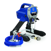
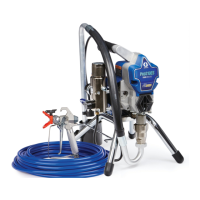
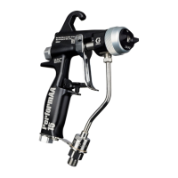
FIG. 1: PerformAA 50 with fluid swivel
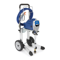
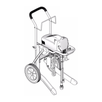
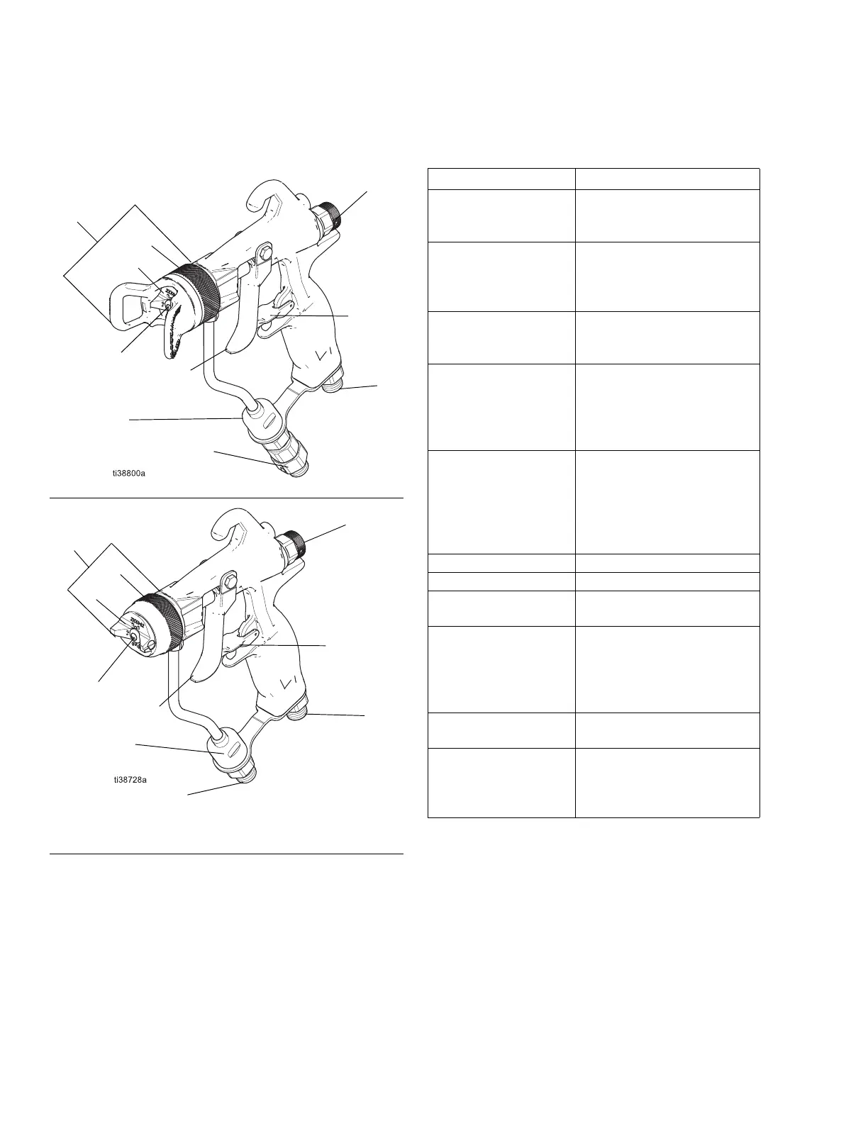
FIG. 2: PerformAA 15 without fluid swivel
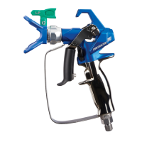
Part Purpose
Trigger Lock (3)
Locks the trigger (9) to
prevent the gun from
spraying.
Spray Tip (7)
Atomizes the fluid and
shapes the pattern width.
See Spray Tip Charts,
page 50.
Air Cap Assembly (8)
Assembled air cap: air cap
(8a), retaining ring (8b), tip
guard, and seals.
Air Cap (8a)
Holds the spray tip (7) and
completes the atomization
of the paint tails. See Air
Cap Selection Guide,
page 54.
Retaining Ring (8b)
Attaches the air cap
assembly to the gun. High
pressure gun retaining rings
include a tip guard to keep
body parts away from the
spray tip.
Trigger (9) Activates the spray gun.
Inline Fluid Filter (14) Provides final fluid filtration.
Fluid Inlet Fitting (15)
1/4-18 npsm for fluid supply
hose.
Gun Air Inlet (16)
1/4-18 npsm (R 1/4-19) inlet
for the gun air supply hose.
Compatible with npsm and
bsp female swivel
connectors.
Fan Adjustment Knob
(21g)
Adjusts fan pattern shape
and width.
Fluid Swivel
Connector (22)
Improves gun
maneuverability. Included
with select models. See
Models, page 3.