Setup
18 312062A
4. Connect feed pumps
a. Install feed pumps (K) in component A and B
supply drums. See F
IG. 1 and FIG. 2, pages 8
and 9.
b. Seal component A drum and use desiccant
dryer (M) in vent.
c. Install agitator (L) in component B drum, if nec-
essary.
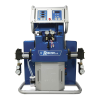
d. Ensure A and B inlet valves (FV) are closed.
e. Connect and tighten component B supply hose
to the 3/4 npt(f) swivel on the component B inlet
valve.
f. Connect and tighten component A supply hose
to the 1/2 npt(f) swivel on the component A inlet
valve.
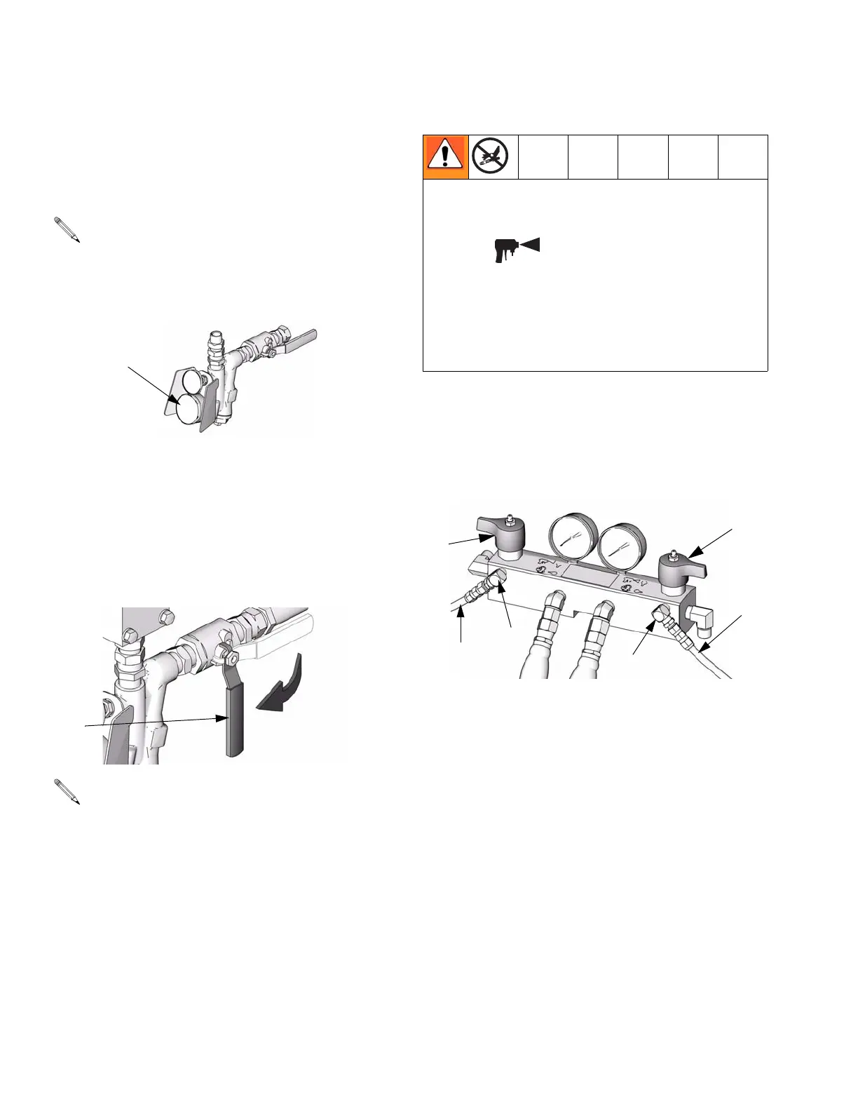
5. Connect pressure relief lines
a. Recommended: Connect high pressure hose
(R) to relief fittings (BA, BB) of both PRES-
SURE RELIEF/SPRAY valves, Route hose back
to component A and B drums. See F
IG. 1, page
8.
b. Alternately: Secure supplied bleed tubes (N) in
grounded, sealed waste containers (H). See
F
IG. 2, page 9.
6. Install Fluid Temperature Sensor (FTS)
The Fluid Temperature Sensor (FTS) is supplied. Install
FTS between main hose and whip hose. See Heated
Hose manual 309572 for instructions.
A minimum feed pressure of 50 psi (0.35 MPa, 3.5
bar) is required at both feed inlet pressure gauges
(FP). Maximum feed pressure is 250 psi (1.75 MPa,
17.5 bar). Maintain A and B feed pressures within
10% of each other.
Supply hoses from feed pumps should be 3/4 in.
(19 mm) ID.
FP
ti10006a
FV
ti9883a
Do not install shutoffs downstream of the PRES-
SURE RELIEF/SPRAY valve outlets (BA, BB). The
valves function as overpressure relief valves when set
to SPRAY . Lines must be open so valves can
automatically relieve pressure when machine is oper-
ating.
If circulating fluid back to the supply drums, use high
pressure hose rated to withstand the maximum work-
ing pressure of this equipment.
ti9880a
BA
BB
R
R
SB
SA
 Loading...