130
Programming examples – Fixed-wing models
particularly good choice for this purpose is a two-
function stick switch, which your local GRAUPNER
Service Centre can install for you.
The selected switch is assigned in the menu …
»Phase assignment« (page 80)
P H A S E A S S I G N M E N T
p r i o r c o m b i
A B C D
4 I < 1 N o r m a l >
S E L
Use the rotary control to select the switch symbol un-
der “B”. After a brief press on the rotary control, ope-
rate the switch you wish to use, e.g. the switch with
the number “4”.
Initially the “normal” phase is assigned to both switch
positions, i.e. ON (I) and OFF ( ), and this is shown
on the right of the screen. Select SEL using the rota-
ry control. After a brief press on the rotary control, ac-
tivate the select list for the phases which you have set
up in the »Phase setting« menu.
For example, you could name the phase for the for-
ward switch position «1 Normal», and for the back po-
sition «2 Landing» (or vice versa). These phase na-
mes now appear in all fl ight phase dependent menus,
and – of course – also in the transmitter’s basic dis-
play.
Now select the «Landing» fl ight phase, and in the
menu …
»Wing mixers« (page 84)
A i l e r o n s 2 > 4 R u d d e r + 0 %
A i l e r o n s 2 > 7 F l a p s + 0 %
B r a k e > 3 E l e v a t o r + 0 %
B r a k e > 6 F l a p s
+ 0 %
B r a k e > 5 A i l e r o n s + 0 %
« L a n d i n g »
S E L
t
s
… set the desired travel of the ailerons when the Ch1
stick (“Brake”) is moved up; this is carried out in the
“Brake 5 aileron” line. Now move to the “Brake
6 fl aps” line with the rotary control pressed in, where
you can enter the desired down-fl ap defl ection when
the Ch1 stick is operated. This wing fl ap confi gurati-
on is termed the “crow” or “butterfl y” position; see also
page 87.
In the «Landing» fl ight phase the Channel 1 stick is –
of course – required not to switch the electric motor
on. To prevent this happening, move to the menu …
»MIX-only channel« (page 108)
M I X O N L Y C H A N N E L
M I X o n l y
n o r m a l
1 2
3 4
5 6
7 8 9 1 0
1 1 1 2
… and set Channel 1 to “MIX only” with a brief press
on the rotary control.
However, since the motor is to be operated by Ch1 in
the «Normal» fl ight phase, but the »MIX-only chan-
nel« menu cannot be set separately for each fl ight
phase, we have to move to the menu …
»Free mixers« (page 102)
L i n e a r M I X 1 T r C 1 C 1 = >
L i n e a r M I X 2 ? ? ? ? - - - -
L i n e a r M I X 3
? ? ? ? - - - -
L i n e a r M I X 4 ? ? ? ? - - - -
t y p e f r o m t o A d j u s t
S E L
t
S E LS E L
… and create this facility.
This is achieved by programming a free mixer, such
as LinearMIX 1, from “Ch1 Ch1”. On the second
page of the menu set the mixer input to +100% on
both sides (symmetrically).
L i n e a r M I X 1 C 1 C 1
M i x i n p u t O f f s e t
+ 1 0 0 %
+ 1 0 0 % 0 %
®
O U T P U T
-
+
1 0 0
S T O
A S YS Y M C L R
Why? In the »MIX-only channel« you separated the
control function Ch1 from output 1, so that the servo
at output 1 can only be accessed using mixers (hence
the name “MIX-only channel”). We have now set up
just such a mixer. However, the result is that we have
defeated our efforts thus far – unless we disable it in
the fl ight phase «Landing» (“no” setting) in the menu
…
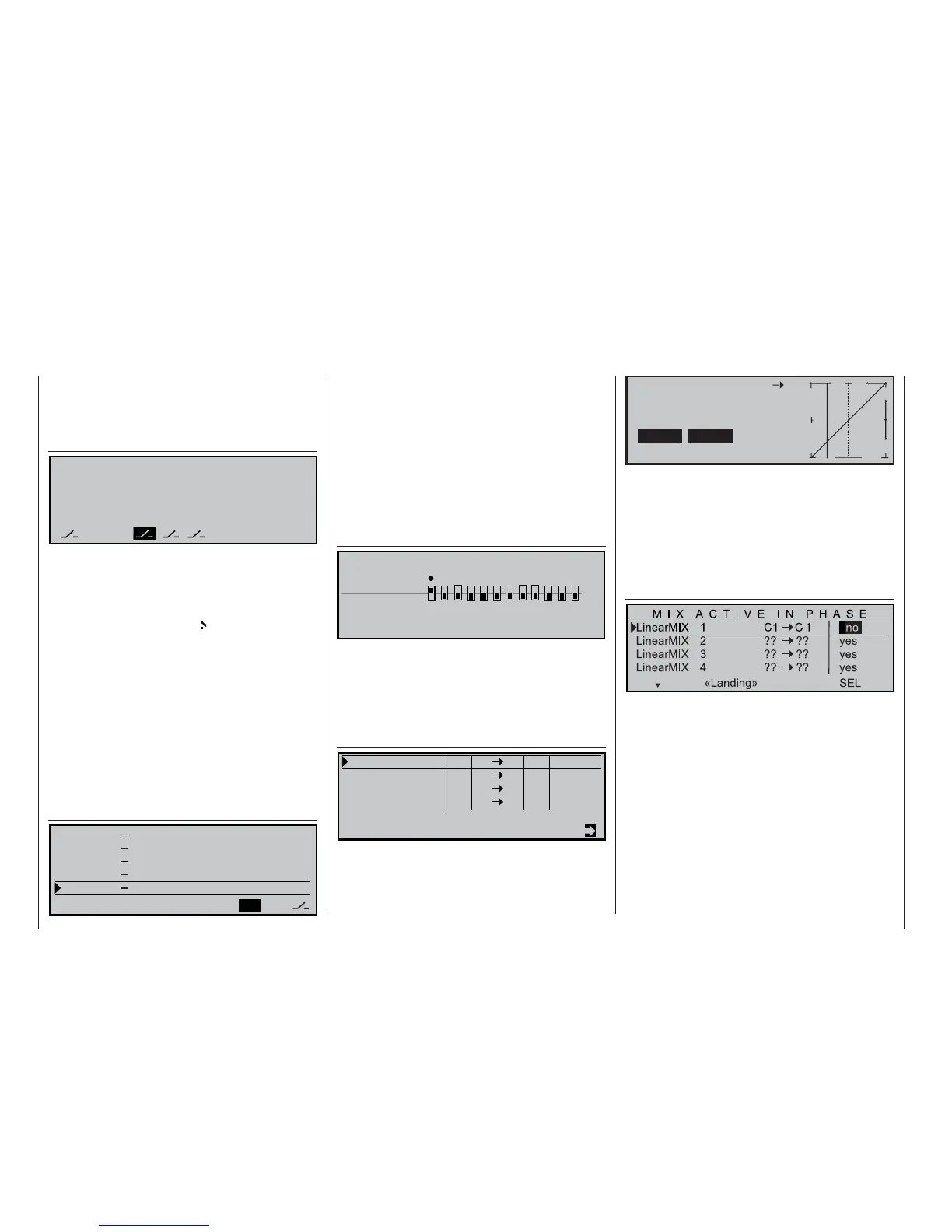
»MIX active/phase« (page 108)
We’re nearly there! Move to the »Servo display«
menu and check your programming: you will fi nd that
the Ch1 stick controls only “servo 1” (speed control-
ler) in the «Normal» fl ight phase, and only the aileron
and fl ap servos in the «Landing» phase … but ser-
vo 1 remains fi xed at 0% in this phase, with the result
that the motor would run at around “half-throttle”!
This problem can be eliminated by setting up a se-
cond linear mixer. Move back to the menu …