140
»MIX-only channel« (page 108)
M I X O N L Y C H A N N E L
M I X o n l y
n o r m a l
1 2
3 4
5 6
7 8 9 1 0
1 1 1 2
… so that the associated servo is not also operated
by the elevator stick!
Many years ago the author operated a model delta
with the mc-20, programmed exactly in this way, with
a butterfl y (crow) system as landing aid, exploiting the
“Brake 5 aileron” and “Brake 6 fl aps” wing mi-
xers to provide complete compensation for pitch trim
changes. In this case the term “ailerons” means the
outboard wing control surfaces, and “fl aps” the in-
board pair of control surfaces. To achieve the same
effect with the mc-22s, move back to the menu …
»Wing mixers« (page 84)
… and enter the values for the up-aileron travel and
the down-fl ap travel in the “Brake 5 aileron” and
“Brake 6 fl aps” lines in such a way that the pitching
moments which occur in fl ight cancel each other out,
Programming examples – Fixed-wing models
i.e. the model’s fl ight attitude remains stable. Howe-
ver, do take care to allow the control surfaces enough
“elbow-room” for the elevator function: this means,
don’t exploit the full servo travel for the butterfl y / crow
system alone.
You can ignore all the other settings in this menu.
A modern sweptback fl ying wing can also be opera-
ted in the same way. Many of these models also fea-
ture inboard and outboard control surfaces: the for-
mer forward of the Centre of Gravity, the latter aft of it.
Defl ecting the inboard control surface(s) down incre-
ases lift and produces an up-elevator effect. Defl ec-
ting them up creates the opposite effect. In contrast,
the outboard ailerons have the reverse effect: a down-
defl ection produces a down-elevator effect, and vice
versa. In this case there are really no limits to what
you can achieve with careful thought and the sophisti-
cated mixers of the mc-22s. This could extend to set-
ting up curve mixers which pass just a small degree
of up / down travel to the outboard pair of control sur-
faces, and only at fairly extreme stick travels. For his
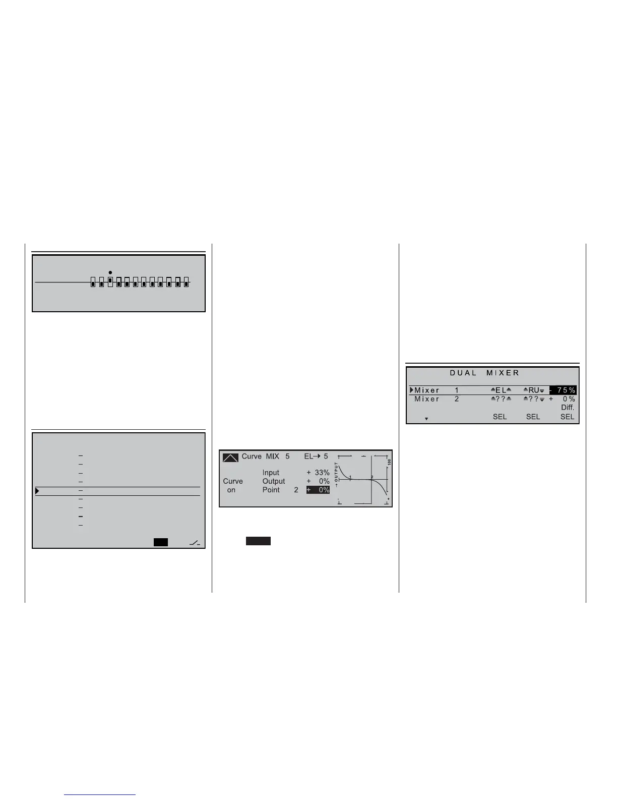
own model this writer uses a curve mixer defi ned by a
total of four reference points, i.e.:
In this example the two reference points 1 and 2 are
set to 0%, the left end-point to +60%, and the right
end-point to -65%; the curve is then rounded by pres-
sing the ENTER button.
Please note that you should be extremely careful
when setting differential travel with such a confi gura-
tion, regardless of the type of servo arrangement you
are using. This is because differential travels tend to
produce an asymmetrical elevator effect on a tail-less
model, rather than the desired adverse yaw reduction.
For this reason it is advisable to start with a differenti-
al setting of 0%, at least for the fi rst few fl ights. When
you are familiar with the model and feel the need to
experiment, it may then be feasible under certain cir-
cumstances to try differential settings deviating from
zero.
For larger models it may be advisable to install wing-
lets fi tted with rudders, i.e. small vertical surfaces at
the wingtips. If these are actuated by two separate
servos, the rudder signal can very easily be “split” by
using a mixer in the menu ...
»Dual mixers« (page 110)
… in which case you can also apply “split” or differen-
tial travel, with the second rudder servo connected to
a free receiver output socket. If you have programmed
the “Delta / fl ying wing” tail type at an earlier stage,
receiver output “5” should still be free. If you have se-
lected the “normal” tail type, output “3” (ELE) should
still be free; this is the one we will use in the following
example.
Select the »MIX-only channel« menu (see above),
or the »Control adjust« menu (if the second ser-
vo is connected to one of the outputs 5 … 12), and
de-couple the “wrong” control function from the cont-
rol channel to which you have connected the second
rudder servo.
The differential travel is necessary in this case, since
the outside rudder turns through a larger radius than
the inside rudder when the model is fl ying a turn; this
is broadly analogous to the effect of front wheel toe-
A i l e r o n d i f f e r e n c e + 0 %
F l a p d i f f e r e n c e + 0 %
A i l e r o n s 2 > 4 R u d d e r + 0 %
A i l e r o n s 2 > 7 F l a p s +
5 0 %
B r a k e > 3 E l e v a t o r + 0 %
B r a k e > 6 F l a p s - 5 0 %
B r a k e > 5 A i l e r o n s - 6 0 %
E l e v a t o r 3 > 6 F l a p
s + 0 % + 0 %
E l e v a t o r 3 > 5 A i l e r o n + 0 % + 0 %
F l a p s 6 > 3 E l e v a t o r + 0 % + 0 %
F l a p s 6
> 5 A i l e r o n s + 0 % + 0 %
R e d u c t i o n o f d i f f . + 0 %
S E L
t
s