66
Program description: Transmitter controls
Dual Rate / Expo
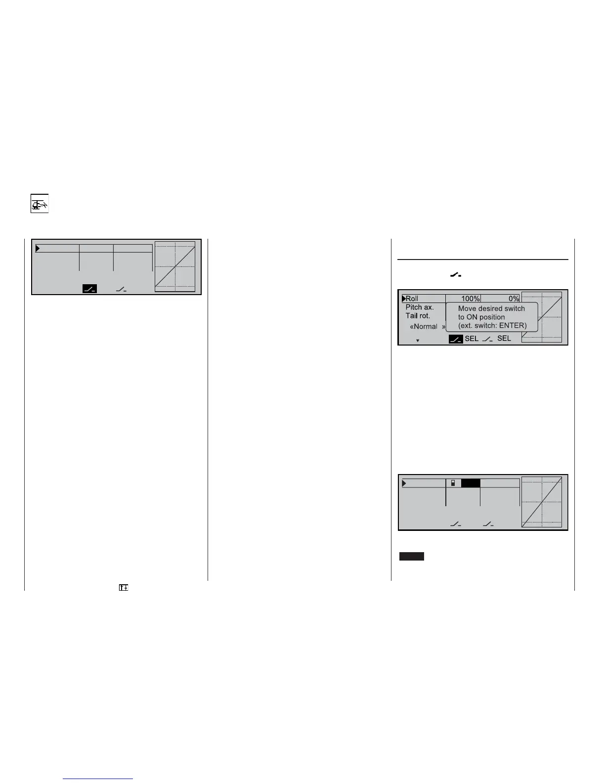
Control characteristics for roll, pitch-axis, tail rotor
R o l l 1 0 0 % 0 %
P i t c h a x . 1 0 0 % 0 %
T a i l r o t . 1 0 0 % 0 %
D U A L E X P 0
S E LS E L
t
The Dual Rate function provides a means of swit-
ching to reduced control travels for the roll, pitch-axis
and tail rotor servos (control functions 2 ... 4) in fl ight
via an external switch; the D/R values can be set se-
parately for different fl ight phases. A separate curve
for control function 1 (motor / collective pitch) can be
set in the »Channel 1 curve« menu, or separately for
throttle and collective pitch in the »Helicopter mixer«
menu. These curves can feature up to fi ve separately
programmable points.
The control travels for each switch position can be set
to any point within the range 0 to 125%, separately
for each direction. Dual Rate works in a similar way to
servo travel adjustment in the »Servo adjustment«
menu, but the Dual Rate function does not affect the
servo directly; instead it affects the corresponding
stick function, regardless of whether this function con-
trols a single servo or multiple servos via any number
of complex mixer and coupling functions.
The exponential control characteristic works in a dif-
ferent way. If you set values greater than 0%, expo-
nential provides fi ne control of the model around the
centre position of the primary control functions (roll,
pitch-axis and tail rotor), without forfeiting full travel
at the end-points of stick travel. If you set values lo-
wer than 0%, travel is increased around the neutral
position, and diminishes towards the extremes of tra-
vel. The degree of “progression” can be set within the
range -100% to +100%; 0% equates to normal, linear
control characteristics.
A further application for exponential is to improve the
linearity of rotary-output servos, which are the stan-
dard nowadays. The movement of the control surface
is inevitably non-linear with a rotary servo, as the li-
near movement of the output disc or lever diminishes
progressively as the angular movement increases,
i.e. the rate of travel of the control surface is reduced
steadily towards the extremes, dependent upon the
position of the linkage point on the output disc or le-
ver. You can compensate for this effect by setting an
Expo value greater than 0%, with the result that the
angular travel of the output device increases dispro-
portionately as stick travel increases.
Like Dual Rates, the Expo setting applies directly to
the corresponding stick function, regardless of whe-
ther this controls a single servo or multiple servos via
any number of complex mixer and coupling functions.
The Expo function can also be programmed asymme-
trically, can be switched on and off in fl ight if a switch
is assigned to it, and can also be programmed sepa-
rately for different fl ight phases.
Since switches can be assigned to the Dual Rate and
Expo functions with complete freedom, it is also pos-
sible to operate several functions using one and the
same switch. The result of this is that Dual Rates and
Expo can be controlled simultaneously using a single
switch, and this can be advantageous, especially with
very high-speed models. See below for more details.
The graphic screen displays the curve characteristics
directly. When you select the appropriate menu line,
the central vertical line follows the movement of the
stick concerned, so that you can easily observe how
the curve value changes with control travel.
Different Dual Rate and Expo settings in fl ight
phases:
If you wish to try out different fl ight phases in the
»Auxiliary switch«, »Phase setting« and »Phase
assignment« menus, the assigned fl ight phase name
is displayed at bottom left of the screen, e.g. «Nor-
mal». Operate the appropriate switch to move bet-
ween fl ight phases.
Dual Rate function
If you wish to switch between two possible D/R set-
tings, select the
fi eld and assign an external
switch ...
... or one of the control switches G1 ... G4 (or one of
the inverted control switches G1i ... G4i), as descri-
bed on page 30.
If you use one of the “G” switches, the stick position it-
self acts as the switch. In this case it is essential (!) to
move to the »Control switch« menu and assign the
control switch to the stick you wish to use. The assig-
ned switch appears in the screen display together
with a switch symbol which indicates the direction of
operation when you move the switch.
Select the SEL fi eld to change the Dual Rate value,
and use the rotary control in the inverse video fi eld to
set the values for each of the two switch positions se-
parately, e.g. in the “normal” fl ight phase:
R o l l 2 1 2 5 % 0 %
P i t c h a x . 1 0 0 % 0 %
T a i l r o t . 1 0 0 % 0 %
« N o r m a l » D U A L E X P O
S E LS E L
t
The Dual Rate curve is shown simultaneously in the
graph.
(CLEAR = 100%.)