67
Program description: Transmitter controls
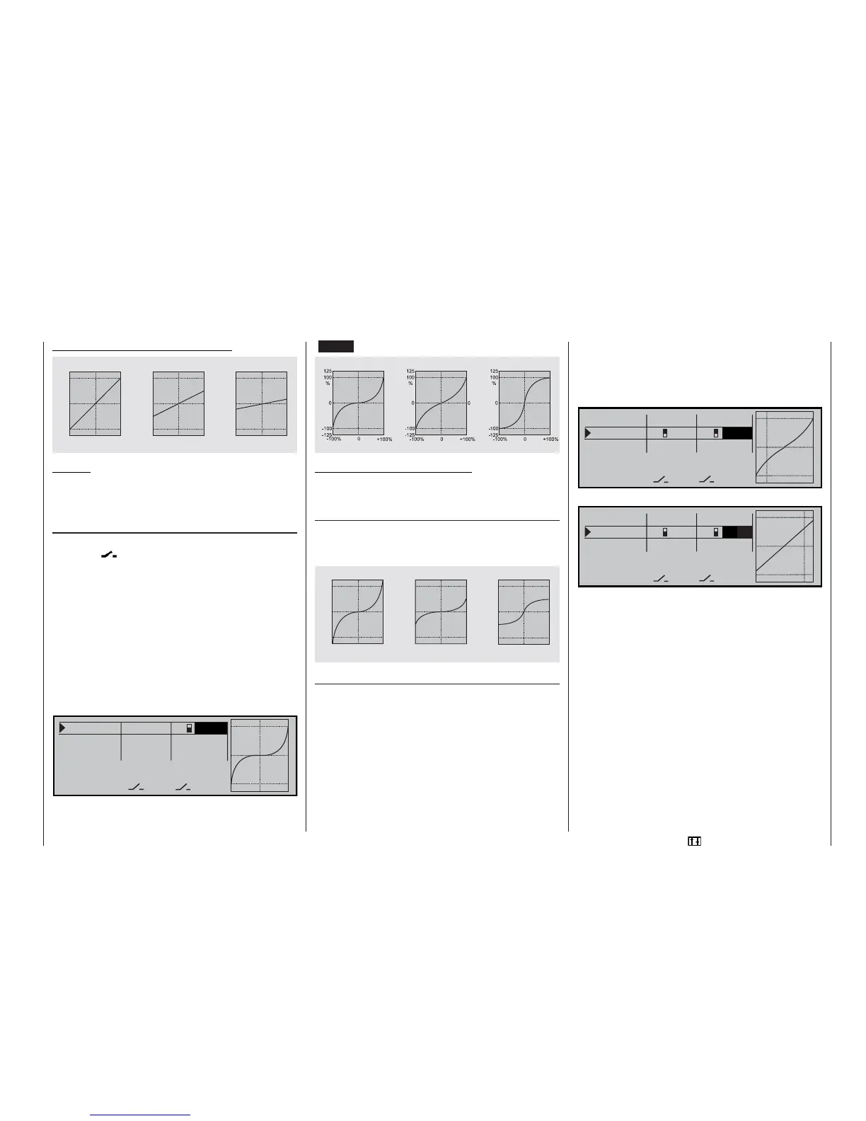
Examples of different Dual Rate values:
Caution:
The Dual Rate value should always be at least 20%
of total control travel, otherwise you could lose all
control of that function.
Exponential function
If you wish to switch between two possible settings,
select the
fi eld and assign an external switch or
one of the control switches, as described on page 30.
The assigned switch appears in the screen display to-
gether with a switch symbol which indicates the direc-
tion of operation when you move the switch.
For example, the system enables you to fl y with a li-
near curve characteristic in the one switch position,
and to operate with a pre-set value other than 0% in
the other switch position.
To change the Expo value, fi rst select the SEL fi eld,
then use the rotary control in the inverse video fi eld to
set separate values for each of the two switch positi-
ons, e.g. in the “normal” fl ight phase:
R o l l 1 0 0 % 2 + 1 0 0 %
P i t c h a x . 1 0 0 % 0 %
T a i l r o t . 1 0 0 % 0 %
« N o r m a l » D U A L E X P O
S E L
S E L
t
The Expo curve is displayed simultaneously in the
graph.
(CLEAR = 0%.)
Examples of different Expo values:
In these examples the Dual Rate value is 100% in
each case.
Combination of Dual Rate and Expo
If you have assigned Dual Rates and Expo to the
same switch, both functions are switched simultane-
ously, e.g.:
Asymmetrical setting of Dual Rate and Expo
If you wish to set asymmetrical Dual Rate and / or
Expo values, i.e. varying according to the direction of
stick movement, you must defi ne one of the control
switches G1 ... G4 or G1i ... G4i when selecting swit-
ches. Select the relevant control function, e.g. “Pitch-
axis”, and select a control switch, e.g. “G1”. In the
»Control switch« menu you could assign, say, “Cont-
rol 3” (= pitch-axis stick) to this control switch, but lea-
ve the switching point at the neutral position of the
stick.
Now select the SEL fi eld in the “DUAL” or “EXPO” co-
lumn. Move the “pitch-axis” stick to the appropriate
end-point, and enter the Dual Rate and / or Expo va-
lue for each side of neutral in the inverse fi eld using
the rotary control, e.g. for:
“pitch-axis, back”:
R o l l 1 0 0 % 0 %
P i t c h a x . G 1 1 0 0 % G 1 + 3 0 %
T a i l r o t . 1 0 0 % 0 %
D U A L E X P O
S E LS E L
t
s
and “pitch-axis, forward”:
R o l l 1 0 0 % 0 %
P i t c h a x . G 1 9 0 % G 1
0 %
T a i l r o t . 1 0 0 % 0 %
D U A L E X P O
S E LS E L
t
s
The dotted vertical line shows the current pitch-axis
stick position.
0
1 0 0
1 2 5
%
+ 1 0 0 %
- 1 0 0 % 0
- 1 0 0
- 1 2 5
0
1 0 0
1 2 5
%
+ 1 0 0 %
- 1 0 0 %
0
- 1 0 0
- 1 2 5
+ 1 0 0 %
- 1 0 0 % 0
0
1 0 0
1 2 5
%
- 1 0 0
- 1 2 5
Dual Rate = 100%
Dual Rate = 50% Dual Rate = 20%
Servo travel
Servo travel
Servo travel
Stick defl ection Stick defl ection Stick defl ection
Expo = +100%
Expo = +50% Expo = -100%
Servo travel
Servo travel
Servo travel
Stick defl ection Stick defl ection Stick defl ection
+ 1 0 0 %
- 1 0 0 %
0
+ 1 0 0 %
- 1 0 0 % 0
+ 1 0 0 %
- 1 0 0 % 0
0
1 0 0
1 2 5
%
- 1 0 0
- 1 2 5
0
1 0 0
1 2 5
%
- 1 0 0
- 1 2 5
0
1 0 0
1 2 5
%
- 1 0 0
- 1 2 5
Expo = +100%, D/R = 125%
Expo = +50%, D/R = 50% Expo = -100%; D/R = 50%
Servo travel
Servo travel
Servo travel
Stick defl ection Stick defl ection Stick defl ection