6 - 27
5. Visually inspect the wear surfaces of the valve
plate, cylinder block and slippers for damage.
Check to be sure pistons move free in bores.
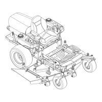
6. Remove the thrust plate from the counterbore in
the swashplate. Visually inspect both sides for
damage and flatness.
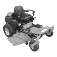
7. Lift out the motor (lower) cylinder block assembly,
Figure 28. This is the same for both pump and
motor. The pistons may come out of the cylinder
bores, however, there is no special orientation of
the piston to bore that needs to be maintained.
NOTE: Do not attempt to disassemble the spring and
other parts from the center bore of the cylinder block.
The entire assembly should be replaced if any of its
components are damaged.
8. Visually inspect the wear surfaces of the valve
plate, cylinder block and slippers for damage.
Check to be sure pistons move free in bores.
9. Remove the two cap screws then remove the fixed
swashplate from the counterbore in the housing.
Visually inspect the wear surface for damage.
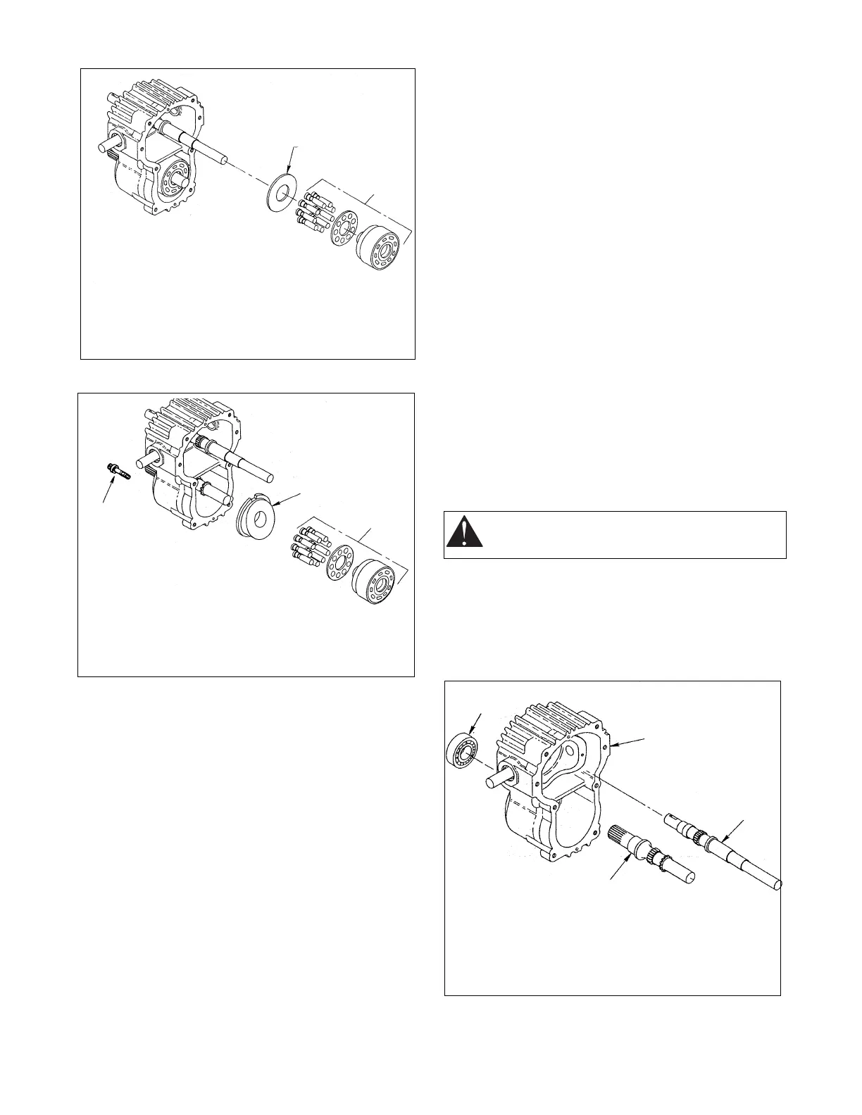
10.The pump shaft and motor shaft can be removed
by pressing them out through the large cavity of the
housing, Figure 29.
11.The motor shaft bearing is removed by pressing
out toward the front of the housing. Replace the
bearing if necessary.
12.Visually inspect the needle bearings and replace if
necessary by pressing them out of the center
section, Figure 30.
NOTE: When replacing the bearings, press into the
center section leaving 3/32" to 1/8" of bearing protrud-
ing beyond the face. The valve plates pilot on these
bearings.
13.Place the housing with the large cavity up. Use
care not to damage the housing. Place a 3/16"
diameter punch in the control shaft and tilt the
swashplate to its full angle (15 degrees, full
forward), Figure 31.
14.Use a second 3/16" diameter punch and drive out
the single pin in the trunnion shaft until it hits the
housing.
15.Drive both pins out of the control shaft until the first
pin contacts the housing. Twist the swashplate
(control shaft) back toward neutral and the first pin
and the pin on the trunnion shaft side should fall
into the housing.
Figure 27
1. Thrust Plate
2. Cylinder Block Assembly
1
2
Figure 28
1. Cap Screw
2. Swashplate
3. Cylinder
Block Assembly
1
2
3
CAUTION: Do not continue to drive the pin or
the housing will be damaged.
1
2
3
4
Figure 29
1. Bearing
2. Housing
3. Pump Shaft
4. Motor Shaft