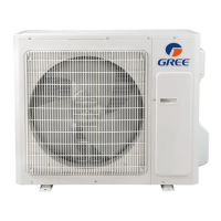
GREE DC INVERTER HEAT PUMP CONDENSING UNIT
21
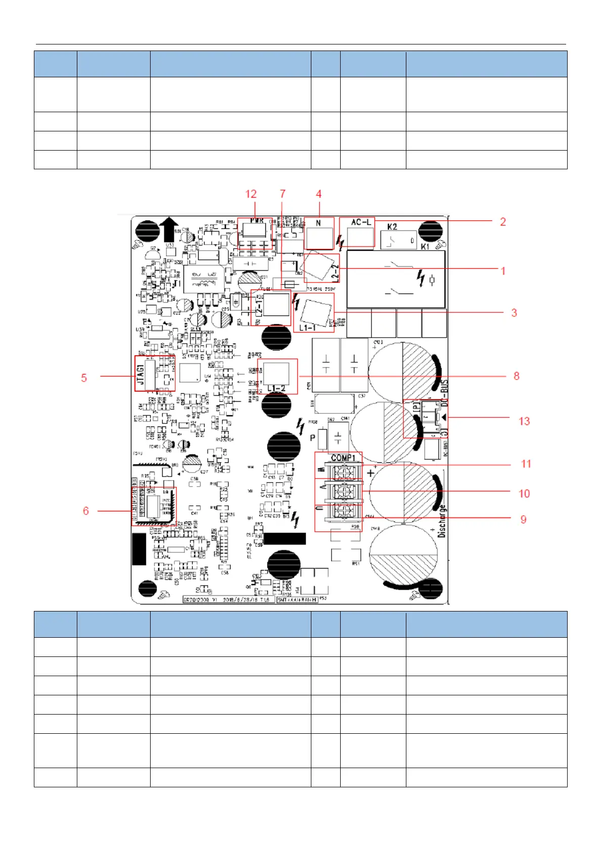
Communication terminal, same with
COMM1
Compressor V phase terminal
Drive power supply terminal
Compressor W phase terminal
Programming interface (for testing)
Power discharge terminal (for testing)
Model: GUD60W/A-D
PFC induction wire (blue)
PFC induction wire (white)
Compressor U phase terminal
PFC induction wire (brown)
Compressor V phase terminal
Compressor W phase terminal
Programming interface (for testing)
Drive power supply terminal
Communication terminal, same with
COMM
Power discharge terminal (for testing)
PFC induction wire (yellow)
 Loading...